NVMe/TCP Configuration and Management
High-performance block storage is a critical requirement for modern cloud-native workloads — databases, virtual machines, and containerised applications all demand low-latency, high-throughput access to persistent volumes. Ceph now supports NVMe over Fabrics (NVMe-oF) with a TCP transport, enabling clients to access Ceph RADOS Block Device (RBD) images as NVMe namespaces over a standard IP network — without specialised hardware.
This blog post walks through how to configure and manage NVMe/TCP in Ceph using the Ceph Dashboard, covering the complete lifecycle: deploying the nvmeof service, creating and managing Gateway Groups, exploring the gateway detail view, and understanding the Subsystems and Namespaces tabs that complete the NVMe-oF setup.
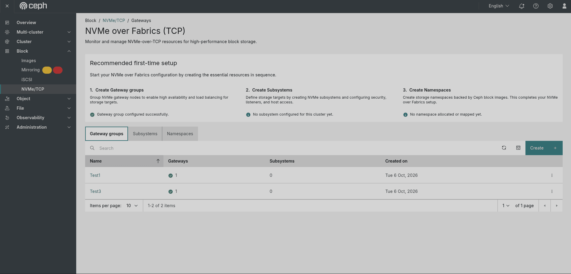
 Figure: The Block → NVMe/TCP → Gateways landing page, showing the recommended first-time setup sequence and two existing gateway groups (Test1, Test3).
Overview: The Three-Step Setup Sequence ¶
When you navigate to Block → NVMe/TCP in the Ceph Dashboard, the page opens on the Gateway groups tab and displays a Recommended first-time setup banner that guides you through the three sequential steps required to get NVMe-oF working:
| Step | Action | Status |
|---|---|---|
| 1. Create Gateway groups | Group NVMe gateway nodes to enable high availability and load balancing for storage targets. | ✅ Gateway group configured successfully. |
| 2. Create Subsystems | Define storage targets by creating NVMe subsystems and configuring security, listeners, and host access. | ℹ No subsystem configured for this cluster yet. |
| 3. Create Namespaces | Create storage namespaces backed by Ceph block images. This completes your NVMe over Fabrics setup. | ℹ No namespace allocated or mapped yet. |
The banner updates its status indicators as you complete each step, making it easy to track progress. The page also exposes three tabs — Gateway groups, Subsystems, and Namespaces — which are the main management surfaces throughout this guide.
Prerequisites: Deploying the NVMe-oF Service ¶
Before creating gateway groups in the Dashboard, the nvmeof orchestrator service must be running on at least one Ceph node. You can deploy it via Administration → Services → Create service in the Dashboard, or using cephadm from the CLI.
Creating the Service from the Dashboard ¶
Navigate to Administration → Services and click Create. In the Create service dialog:
- Type — select
nvmeoffrom the dropdown. - Group name — the name of the gateway group this service instance belongs to (e.g.,
default). - Service name — auto-populated as
nvmeof.<group-name>(e.g.,nvmeof.default). - Unmanaged — leave unchecked so the orchestrator manages the service lifecycle.
- Placement — choose
Hoststo target specific nodes. - Hosts — filter and select the host(s) where the gateway daemon should run.
- Encryption — optionally enable mutual TLS (mTLS) between client and gateway server.
Click Create service to deploy the daemon. Once it is running, the gateway node becomes available for selection when creating a gateway group.
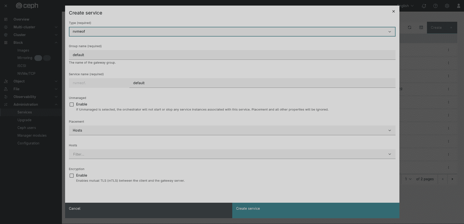 Figure: The Create service dialog with Type set to
nvmeof, Group name default, and Placement set to Hosts.
1. Gateway Groups ¶
1.1 The Gateway Group List ¶
The Gateway groups tab lists all existing gateway groups. Each row shows:
| Column | Description |
|---|---|
| Name | The unique name of the gateway group (e.g., Test1, Test3). Click the name to open the detail view. |
| Gateways | The number of gateway nodes in the group, with a green check indicating all nodes are healthy. |
| Subsystems | The number of NVMe subsystems currently attached to this group. |
| Created on | The date the gateway group was created. |
The ⋮ action menu at the end of each row provides Edit and Delete options.
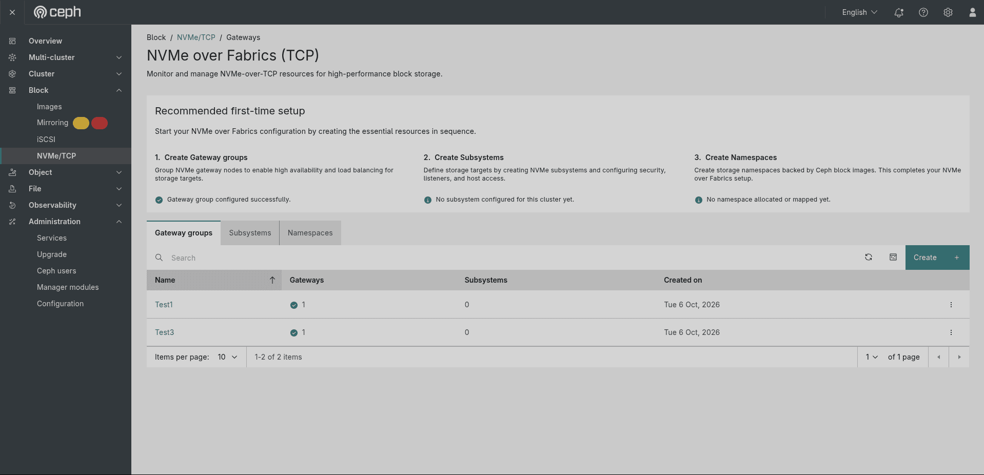 Figure: The Gateway groups tab listing two groups (Test1, Test3), each with 1 healthy gateway node and 0 subsystems, created on Tue 6 Oct, 2026.
1.2 Creating a Gateway Group ¶
Click the Create button in the top-right corner of the Gateway groups tab. This opens the Create Gateway Group page — a logical group of NVMe gateways that hosts connect to for load-balanced access.
Step 1 — Gateway Group Name, Target Nodes and Encryption ¶
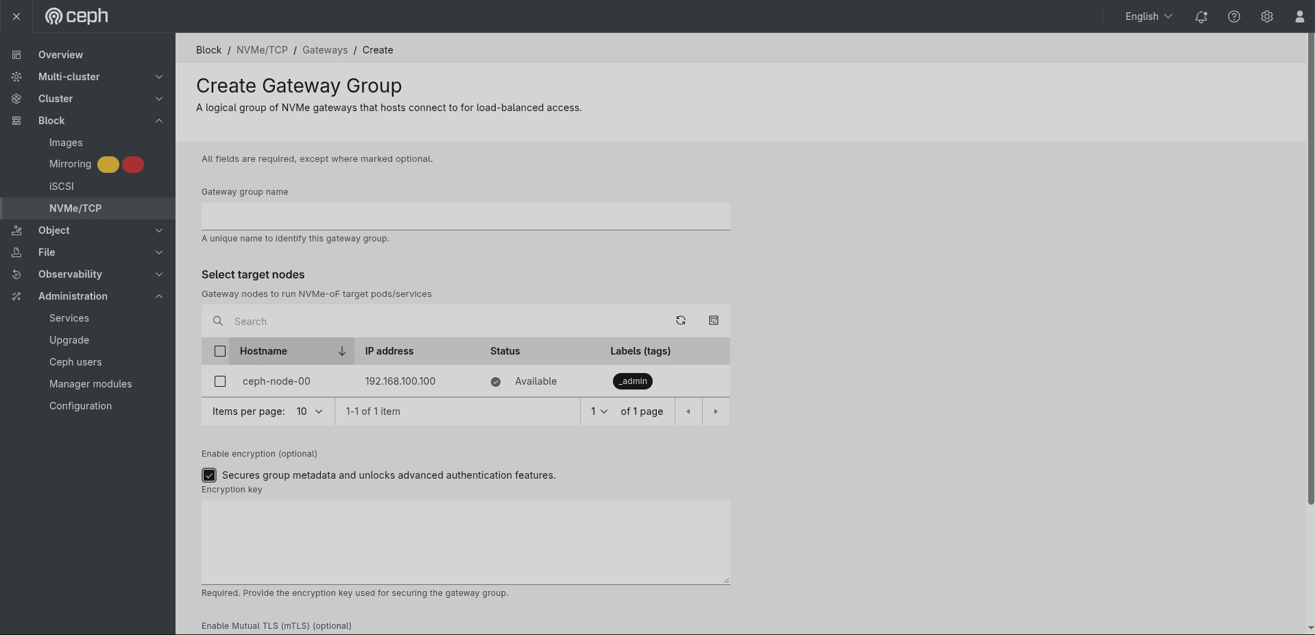 Figure: The Create Gateway Group form — Gateway group name field, Select target nodes table (ceph-node-00, 192.168.100.100, Available, _admin), Enable encryption checkbox checked, and the Encryption key text area with the hint "Required. Provide the encryption key used for securing the gateway group."
Fill in the following fields:
- Gateway group name — a unique name to identify this gateway group (e.g.,
Test1). The hint text reads "A unique name to identify this gateway group."
Select target nodes — the table lists all available Ceph nodes that can run NVMe-oF target pods/services. Check one or more nodes to include them in the group:
| Column | Description |
|---|---|
| Hostname | The Ceph node hostname (e.g., ceph-node-00). |
| IP address | The node's IP address (e.g., 192.168.100.100). |
| Status | Node availability — Available (green) means the node is ready to run the gateway. |
| Labels (tags) | Any cephadm labels applied to the node (e.g., _admin). |
Enable encryption (optional) — checking "Secures group metadata and unlocks advanced authentication features" enables encryption for this gateway group. When the checkbox is ticked, an Encryption key text area appears immediately below it. The field hint reads "Required. Provide the encryption key used for securing the gateway group." — paste or type the encryption key here. This field becomes required as soon as encryption is enabled.
Step 2 — Encryption Key, mTLS, and Certificate Authority (Internal) ¶
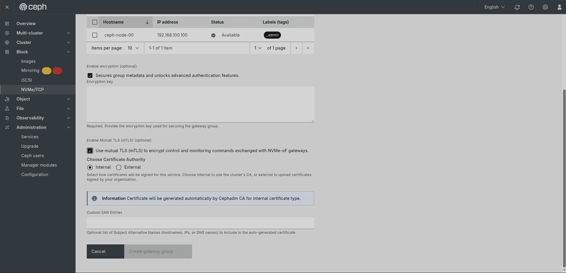 Figure: The Create Gateway Group form scrolled down — the node table (ceph-node-00, unchecked) at the top, Enable encryption checkbox checked with the Encryption key text area below it (hint: "Required. Provide the encryption key used for securing the gateway group."), Enable Mutual TLS checkbox checked, Internal Certificate Authority radio selected, the "Certificate will be generated automatically by Cephadm CA for internal certificate type." information banner, Custom SAN Entries field, and the greyed-out Create gateway group button.
Enable Mutual TLS (mTLS) (optional) — checking "Use mutual TLS (mTLS) to encrypt control and monitoring commands exchanged with NVMe-oF gateways" enables mTLS. When enabled, the Choose Certificate Authority radio buttons appear:
- Internal (default) — the certificate is generated automatically by the Cephadm CA. A blue information banner confirms: "Certificate will be generated automatically by Cephadm CA for internal certificate type." The hint below the CA selection reads: "Select how certificates will be signed for this service. Choose internal to use the cluster's CA, or external to upload certificates signed by your organization." You can optionally provide Custom SAN Entries — an optional list of Subject Alternative Names (hostnames, IPs, or DNS names) to include in the auto-generated certificate. The hint reads "Optional list of Subject Alternative Names (hostnames, IPs, or DNS names) to include in the auto-generated certificate."
- External — upload your own organisation-signed certificates (see Step 3 below).
Once all fields are filled, click Create gateway group to create the group. The button remains greyed out until all required fields are valid.
Step 3 — mTLS with External Certificate Authority ¶
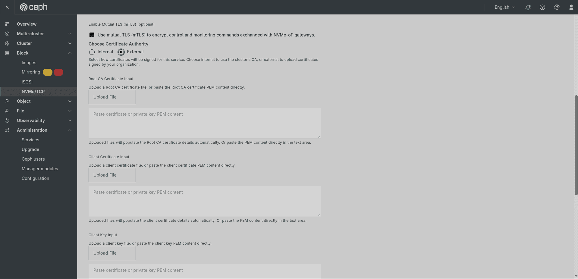 Figure: mTLS with External CA selected — Enable Mutual TLS checkbox checked, External radio selected, Root CA Certificate Input (Upload File + PEM paste area, hint: "Uploaded files will populate the Root CA certificate details automatically. Or paste the PEM content directly in the text area."), Client Certificate Input (Upload File + PEM paste area), and Client Key Input (Upload File + PEM paste area, hint: "Upload a client key file, or paste the client key PEM content directly.").
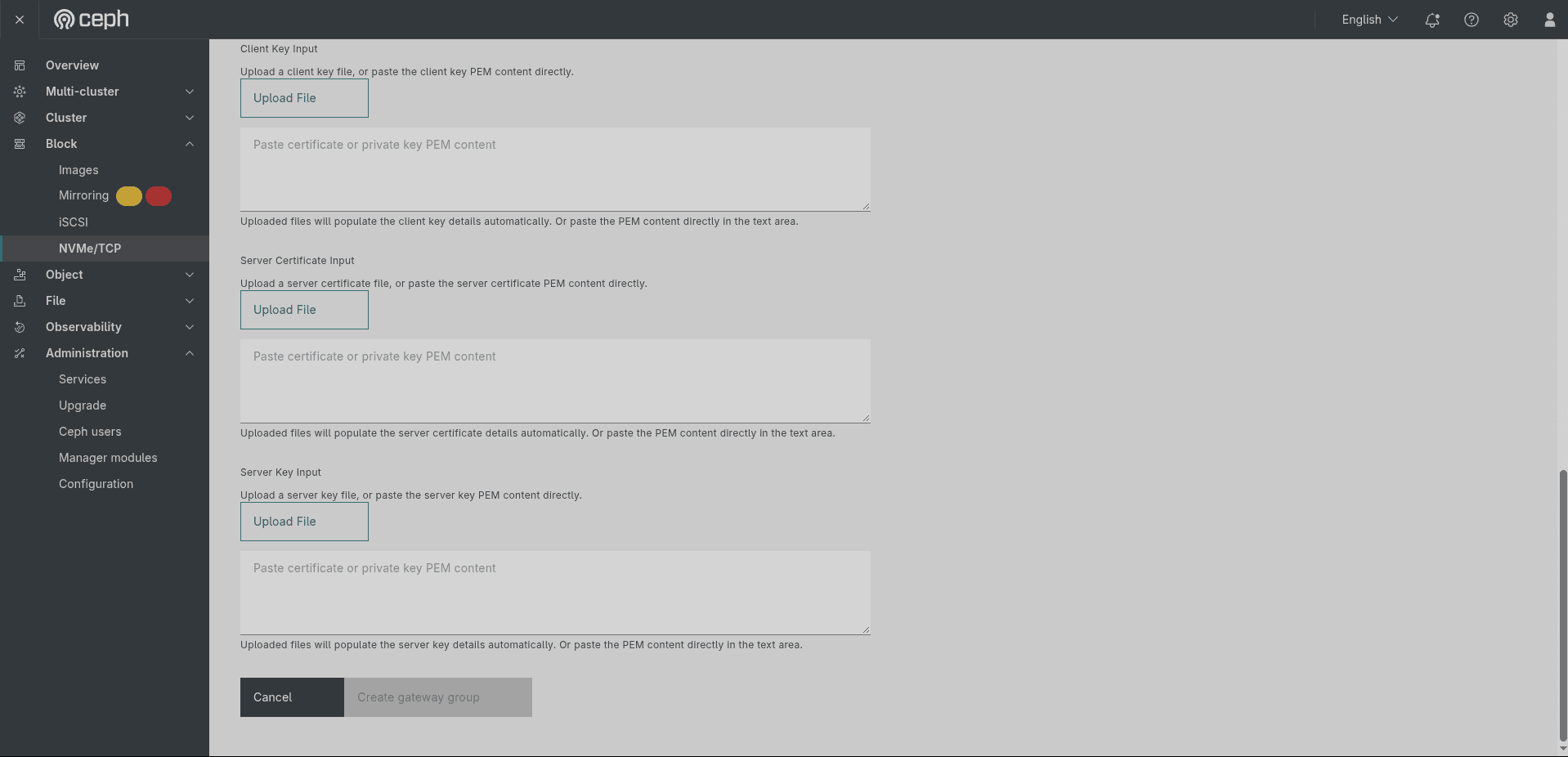 Figure: mTLS External CA continued — Client Key Input paste area at top, Server Certificate Input (Upload File + PEM paste area, hint: "Uploaded files will populate the server certificate details automatically."), Server Key Input (Upload File + PEM paste area), and the Cancel / Create gateway group buttons at the bottom.
When External is selected as the Certificate Authority, the form expands to show five certificate and key upload fields, appearing in this order. Each accepts either a file upload via Upload File or PEM content pasted directly into the text area:
| Field | Description |
|---|---|
| Root CA Certificate Input | Upload or paste the Root CA certificate PEM. Hint: "Upload a Root CA certificate file, or paste the Root CA certificate PEM content directly." |
| Client Certificate Input | Upload or paste the client certificate PEM. Hint: "Upload a client certificate file, or paste the client certificate PEM content directly." |
| Client Key Input | Upload or paste the private key for the client certificate. Hint: "Upload a client key file, or paste the client key PEM content directly." |
| Server Certificate Input | Upload or paste the server certificate PEM. Hint: "Upload a server certificate file, or paste the server certificate PEM content directly." |
| Server Key Input | Upload or paste the private key for the server certificate. Hint: "Upload a server key file, or paste the server key PEM content directly." |
Click Create gateway group at the bottom of the form to save. Click Cancel to discard without saving.
1.3 Gateway Group Detail View ¶
Clicking a gateway group name (e.g., Test3) opens its detail view, which has two tabs in the left sidebar: Overview and Subsystems.
Overview Tab ¶
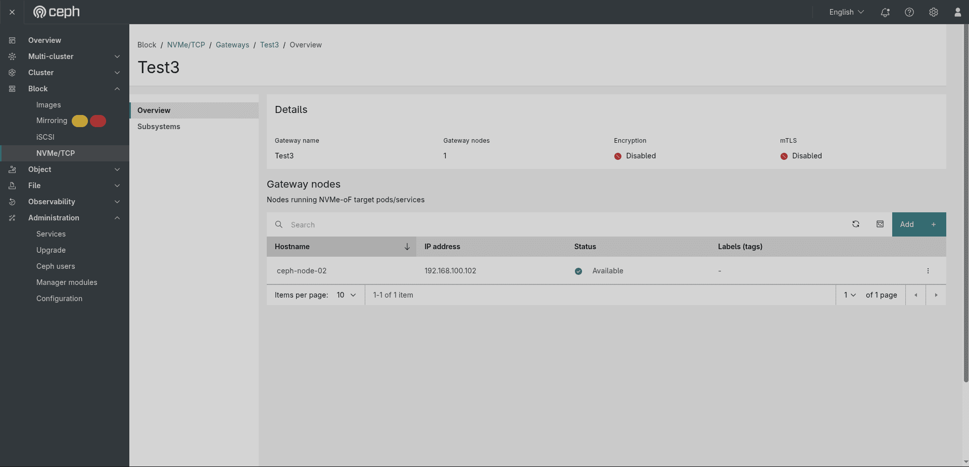 Figure: The Test3 gateway group detail view — Overview tab showing Details (Gateway name, Gateway nodes count, Encryption: Disabled, mTLS: Disabled) and the Gateway nodes table with
ceph-node-02 at 192.168.100.102.
When encryption and mTLS are both enabled the same tab shows green indicators for both fields:
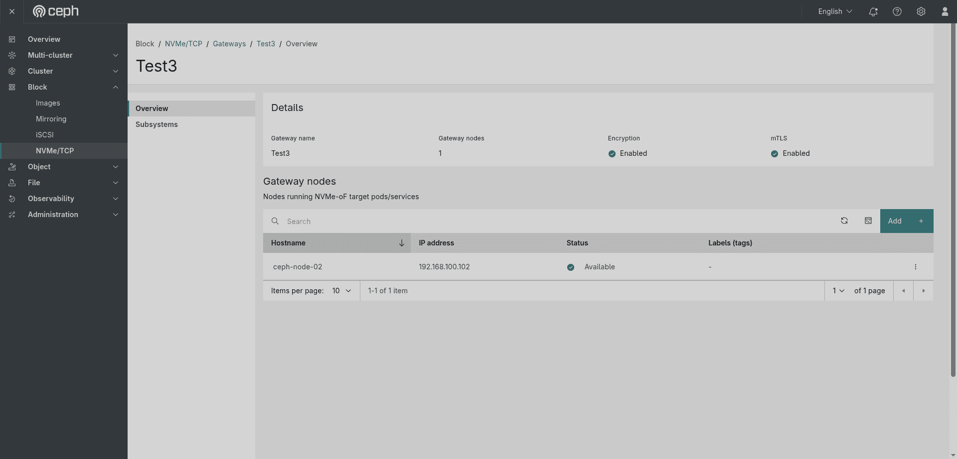 Figure: The Test3 gateway group Overview tab with Encryption: Enabled and mTLS: Enabled — both shown with a green ● indicator.
The Details section at the top of the Overview tab shows four key properties:
| Property | Description |
|---|---|
| Gateway name | The name of the gateway group (e.g., Test3). |
| Gateway nodes | The total number of nodes running NVMe-oF target services in this group (e.g., 1). |
| Encryption | Whether group-level encryption is enabled. A green ● Enabled means it is active; red ● Disabled means it is off. |
| mTLS | Whether mutual TLS is active for control-plane communications. A green ● Enabled means it is active; red ● Disabled means it is off. |
The Gateway nodes table below lists every node assigned to this group:
| Column | Description |
|---|---|
| Hostname | The node's hostname (e.g., ceph-node-02). |
| IP address | The node's IP (e.g., 192.168.100.102). |
| Status | Live health of the gateway daemon — green ● Available means the SPDK target is running. |
| Labels (tags) | Any cephadm labels on the node (- if none). |
An Add button in the top-right corner of the Gateway nodes table lets you expand the group by adding more nodes without recreating it.
Adding Gateway Nodes ¶
Click Add to open the Add gateway nodes dialog — "Select NVMe-oF gateway nodes to associate with this gateway group."
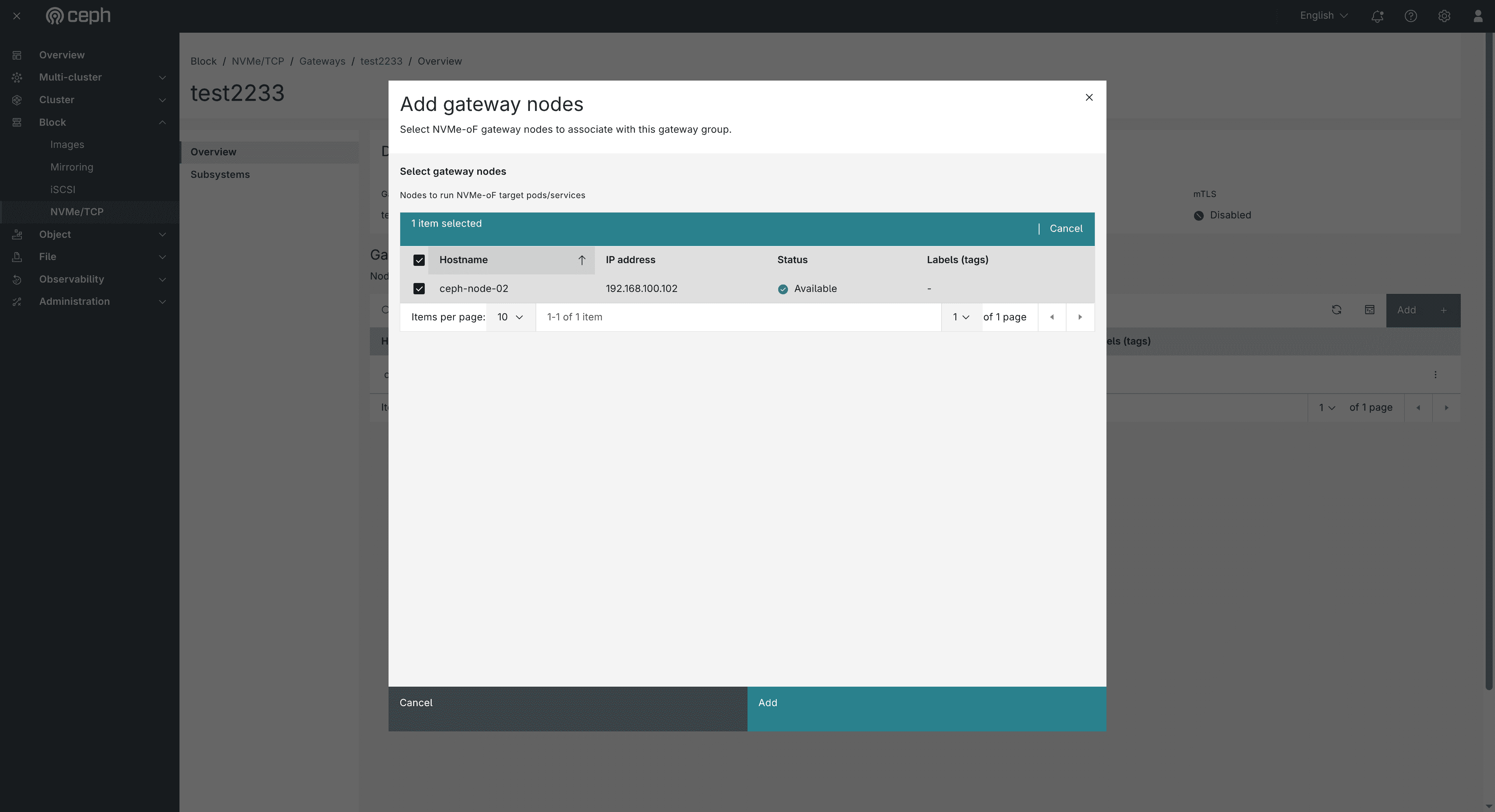 Figure: The Add gateway nodes dialog for gateway group
test2233 — Select gateway nodes table with ceph-node-02 (192.168.100.102, Available) selected. Add is enabled; Cancel closes without changes.
The dialog shows a Select gateway nodes table of hosts that can run NVMe-oF target pods/services:
| Column | Description |
|---|---|
| Hostname | Ceph node hostname (e.g., ceph-node-02). |
| IP address | Node IP address (e.g., 192.168.100.102). |
| Status | Availability — green Available means the node can be added. |
| Labels (tags) | Any cephadm labels on the node. |
Select one or more available nodes, then click Add. A success notification appears (e.g. "Added hosts to gateway group 'test2233'"), and the new nodes show up in the Gateway nodes table. Click Cancel to close without adding anything.
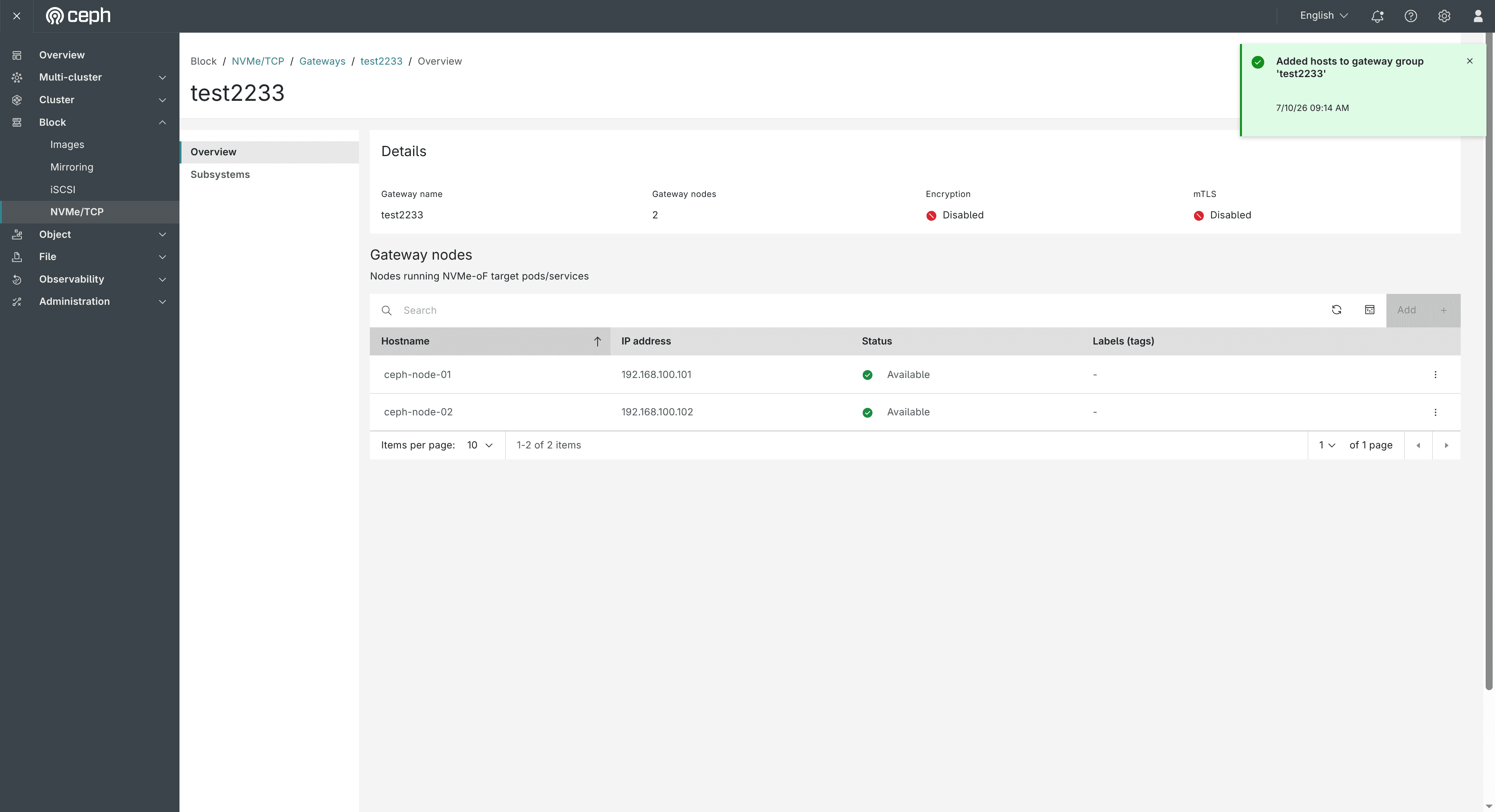 Figure: Gateway group
test2233 Overview after adding a node — Details shows Gateway nodes: 2, success toast "Added hosts to gateway group 'test2233'", and the Gateway nodes table lists ceph-node-01 and ceph-node-02, both Available.
What happens when you add nodes: the Dashboard updates the nvmeof.<group-name> service placement to include the selected hosts. Cephadm then deploys NVMe-oF gateway daemons on those nodes. Once they are healthy, they appear in the Gateway nodes table and can serve listeners/traffic for subsystems in this group. Adding a second (or more) gateway is what enables high availability — a group with only one gateway cannot provide HA. This step does not create subsystems or namespaces; it only expands the gateway capacity of the group.
Note: Only nodes that are not already members of this gateway group (and are available for NVMe-oF) are listed. If every suitable host is already in the group, the table may be empty.
Subsystems Tab ¶
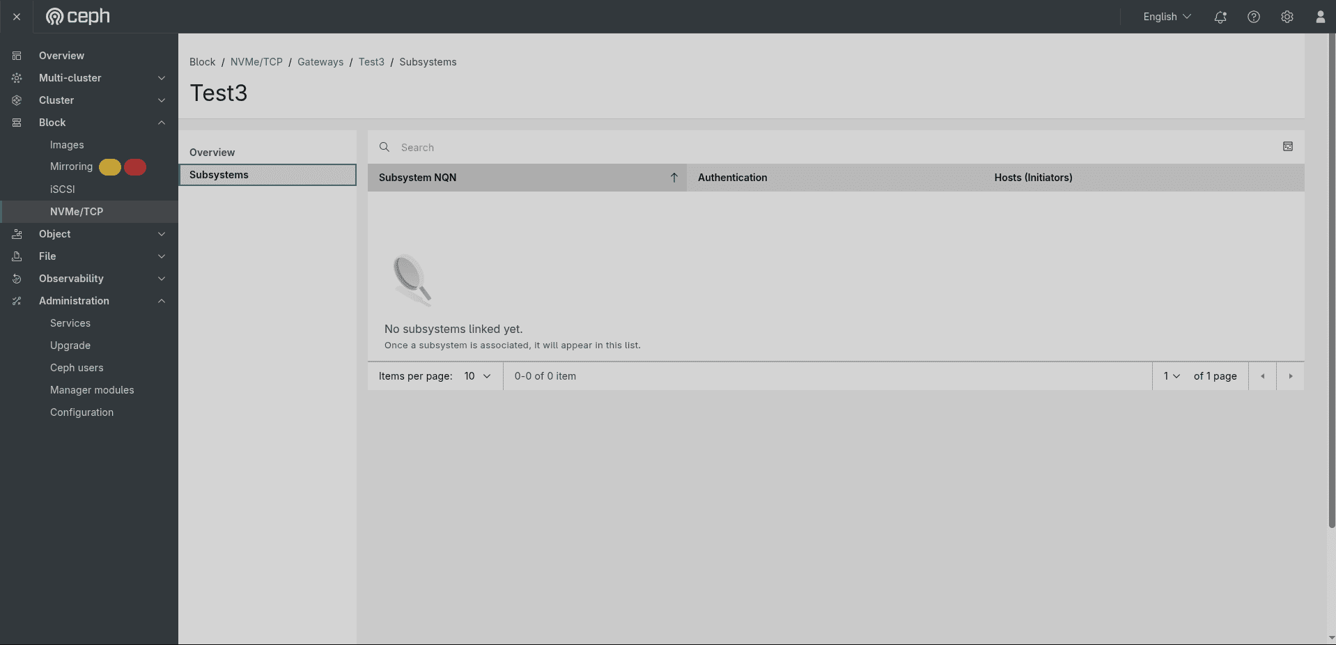 Figure: The Test3 → Subsystems tab showing an empty state — "No subsystems linked yet. Once a subsystem is associated, it will appear in this list." Columns: Subsystem NQN, Authentication, Hosts (Initiators).
The Subsystems tab shows all NVMe subsystems associated with this gateway group. The table columns are:
| Column | Description |
|---|---|
| Subsystem NQN | The NVMe Qualified Name of the subsystem. |
| Authentication | The authentication mode configured on the subsystem. |
| Hosts (Initiators) | The number of initiator hosts permitted to connect. |
When no subsystems have been created yet, the tab shows an empty state: "No subsystems linked yet. Once a subsystem is associated, it will appear in this list." Subsystems are created from the top-level Subsystems tab (see Section 2).
1.4 Editing a Gateway Group ¶
To modify an existing gateway group, click the ⋮ action menu on the gateway group row in the list and select Edit. This opens the Edit Gateway Group page — "Modify gateway group configuration."
Edit Step 1 — Change Nodes and Encryption ¶
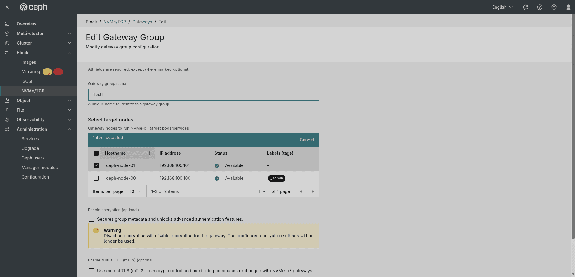 Figure: The Edit Gateway Group form for Test1 — Gateway group name field (pre-filled, editable), Select target nodes table with
ceph-node-01 selected, and the Enable encryption section showing a Warning that disabling encryption will remove all configured encryption settings.
The Edit form is identical in structure to the Create form, with the current values pre-populated:
- Gateway group name — the name field is pre-filled (e.g.,
Test1) and can be changed. - Select target nodes — the currently assigned nodes are pre-selected (blue checkbox). You can add or remove nodes. The table shows all available nodes with their hostname, IP, status, and labels.
- Enable encryption (optional) — if encryption was previously enabled, unchecking it triggers a Warning banner:
"Disabling encryption will disable encryption for the gateway. The configured encryption settings will no longer be used."
- Enable Mutual TLS (mTLS) (optional) — pre-populated with the existing mTLS state.
Edit Step 2 — mTLS and Save ¶
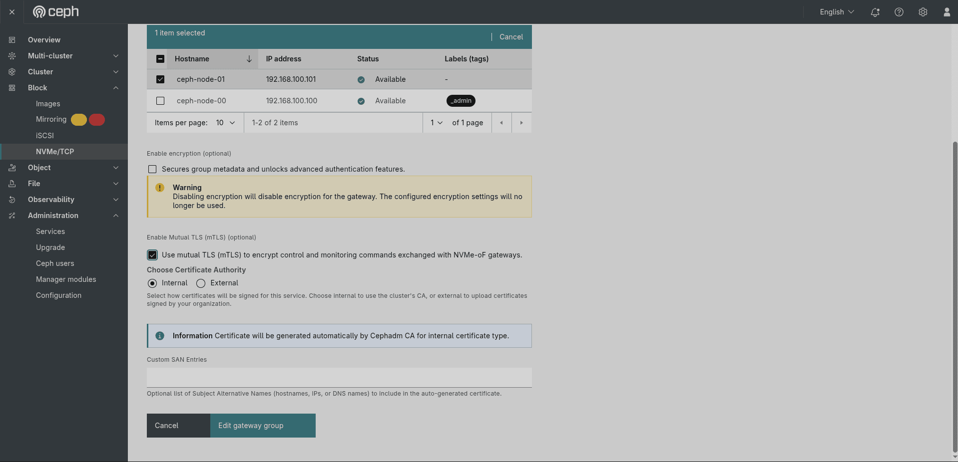 Figure: Edit Gateway Group continued — mTLS checkbox enabled with Internal CA selected, the "Certificate will be generated automatically by Cephadm CA" info banner, Custom SAN Entries field, and the Edit gateway group button.
The mTLS section behaves identically to the Create flow. When Internal CA is selected, the Cephadm CA auto-generates the certificate. Custom SAN entries are optional.
Click Edit gateway group to save the changes, or Cancel to discard them.
1.5 Deleting a Gateway Group ¶
To delete a gateway group, click the ⋮ action menu on the gateway group row and select Delete. A Delete gateway group confirmation dialog appears.
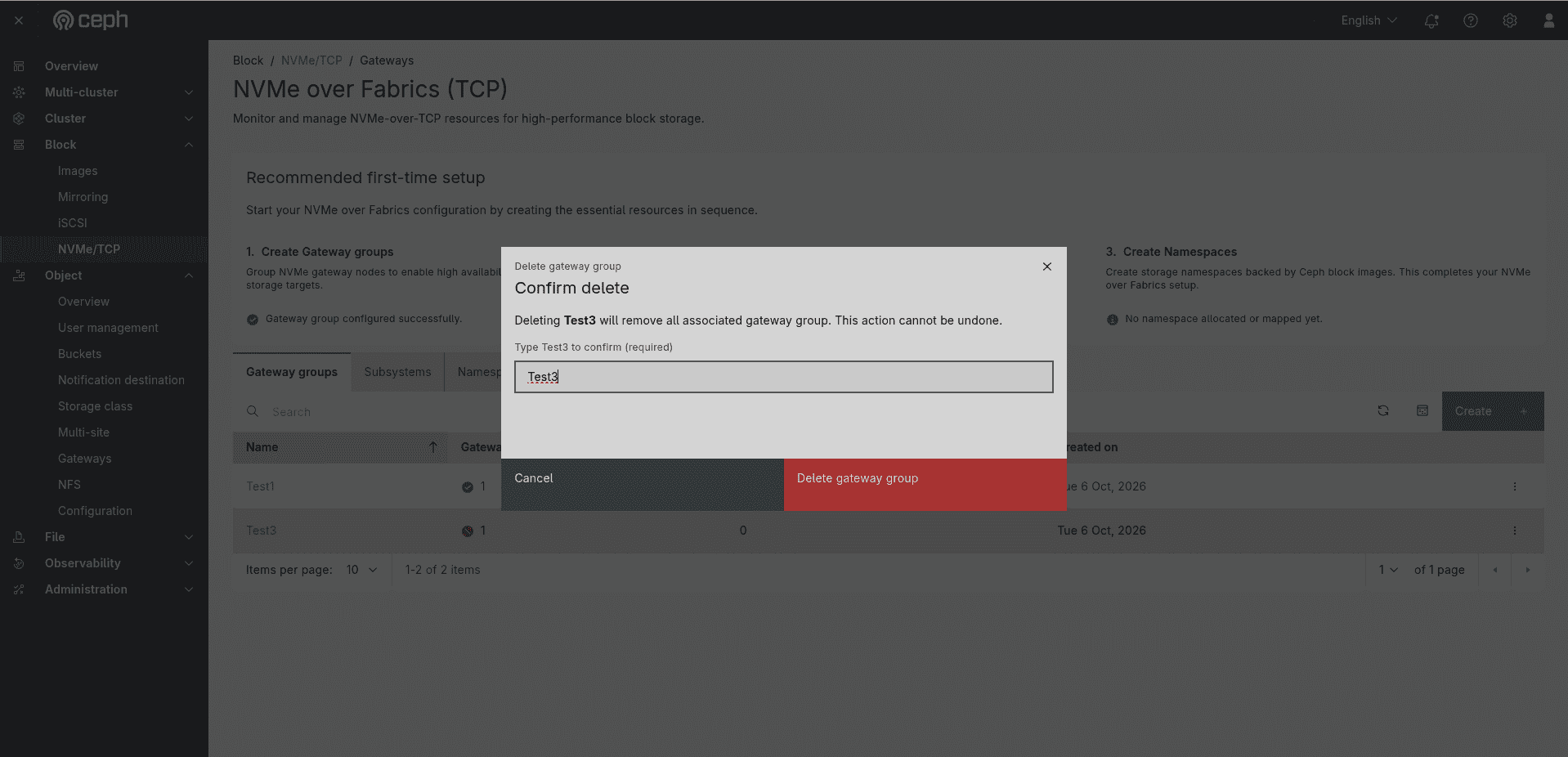 Figure: The Delete gateway group dialog for Test3 — warning that deleting will remove all associated gateway group data and cannot be undone, a text-confirmation field pre-filled with
Test3 (required to type), and the red Delete gateway group button that activates only when the name matches.
The dialog body reads: "Deleting Test3 will remove all associated gateway group. This action cannot be undone." You must type the exact gateway group name (e.g., Test3) into the Name of resource field. The red Delete gateway group button activates only when the typed name matches. Click Cancel to abort.
Note: Before deleting a gateway group, ensure no subsystems or namespaces are attached to it. Deleting a group that still has associated resources may leave those resources in an inconsistent state.
2. Subsystems ¶
Once the gateway group is configured, the next step is to create NVMe subsystems — logical targets that group namespaces and control which hosts can connect.
2.1 The Subsystems Tab ¶
Navigate to the Subsystems tab on the NVMe/TCP landing page.
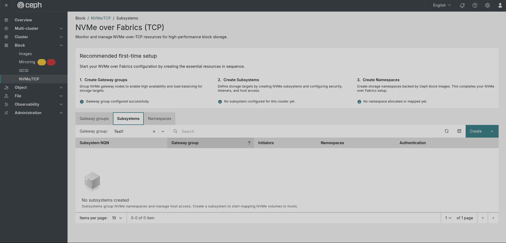 Figure: The Block → NVMe/TCP → Subsystems tab with Gateway group: Test1 filter applied — empty state: "No subsystems created. Subsystems group NVMe namespaces and manage host access." Columns: Subsystem NQN, Gateway group, Initiators, Namespaces, Authentication.
The tab provides a Gateway group dropdown filter to scope the view to one group. The table columns are:
| Column | Description |
|---|---|
| Subsystem NQN | The globally unique NVMe Qualified Name for the subsystem. Click to open the detail view. |
| Gateway group | The gateway group routing traffic for this subsystem. |
| Initiators | The number of host initiators allowed to connect. |
| Namespaces | The number of block namespaces exposed through this subsystem. |
| Authentication | The authentication mode — a ⚠ orange warning icon appears when set to No authentication. |
2.2 Creating a Subsystem ¶
Click Create on the Subsystems tab. This opens the Create Subsystem wizard — "Subsystems define how hosts connect to NVMe namespaces and ensure secure access to storage." The wizard has four steps shown in the left sidebar: Subsystem details, Host access control, Authentication, and Review.
Step 1 — Subsystem Details ¶
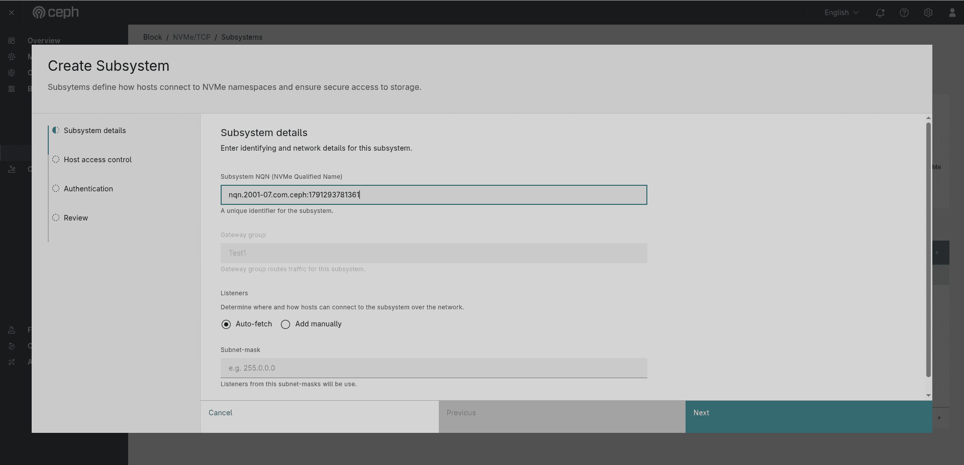 Figure: Create Subsystem wizard — Subsystem details step. Fields: Subsystem NQN (pre-filled
nqn.2001-07.com.ceph:1791293781361), Gateway group (read-only, Test1), Listeners (Auto-fetch / Add manually radio), Subnet-mask. Navigation: Cancel / Previous / Next.
Fill in the following fields:
- Subsystem NQN (NVMe Qualified Name) — a unique identifier for the subsystem (e.g.,
nqn.2001-07.com.ceph:1791293781361). The hint reads "A unique identifier for the subsystem." An NQN is auto-generated but can be edited. Append a descriptive suffix (e.g.,.Test1) for clarity. - Gateway group — read-only, automatically set to the currently selected gateway group (e.g.,
Test1). The hint reads "Gateway group routes traffic for this subsystem." - Listeners — determines where and how hosts can connect to the subsystem over the network:
- Auto-fetch (default) — listeners are automatically derived from the gateway group nodes.
- Add manually — specify listener addresses manually.
- Subnet-mask (optional) — when Auto-fetch is selected, you can optionally restrict which gateway node addresses are used by providing a subnet mask (e.g.,
255.0.0.0). The hint reads "Listeners from this subnet-masks will be use."
Click Next to proceed.
Step 2 — Host Access Control ¶
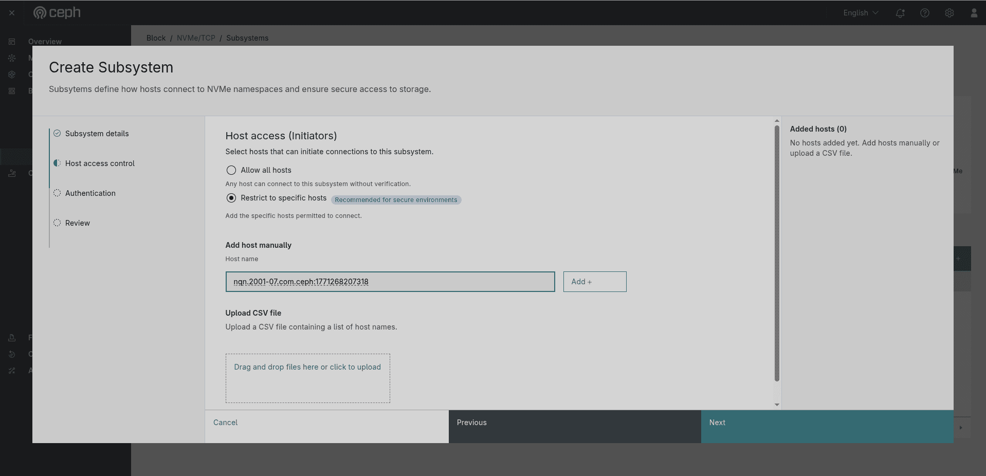 Figure: Create Subsystem wizard — Host access control step. Options: Allow all hosts / Restrict to specific hosts (Recommended for secure environments badge). Add host manually field with NQN input and Add + button. Upload CSV file drop zone. Right panel: Added hosts (0) — "No hosts added yet."
Configure which initiators can connect:
- Allow all hosts — any host can connect to this subsystem without verification.
- Restrict to specific hosts (recommended, shown with a Recommended for secure environments badge) — only the hosts you explicitly add are permitted. The hint reads "Add the specific hosts permitted to connect."
When Restrict to specific hosts is selected, two input methods appear:
- Add host manually — enter the host NQN (e.g.,
nqn.2001-07.com.ceph:1771268207318) in the Host name field and click Add +. Added hosts appear in the Added hosts panel on the right. - Upload CSV file — drag and drop a CSV file containing a list of host NQNs, or click the upload zone to browse. The hint reads "Upload a CSV file containing a list of host names."
Click Next to proceed.
Step 3 — Authentication ¶
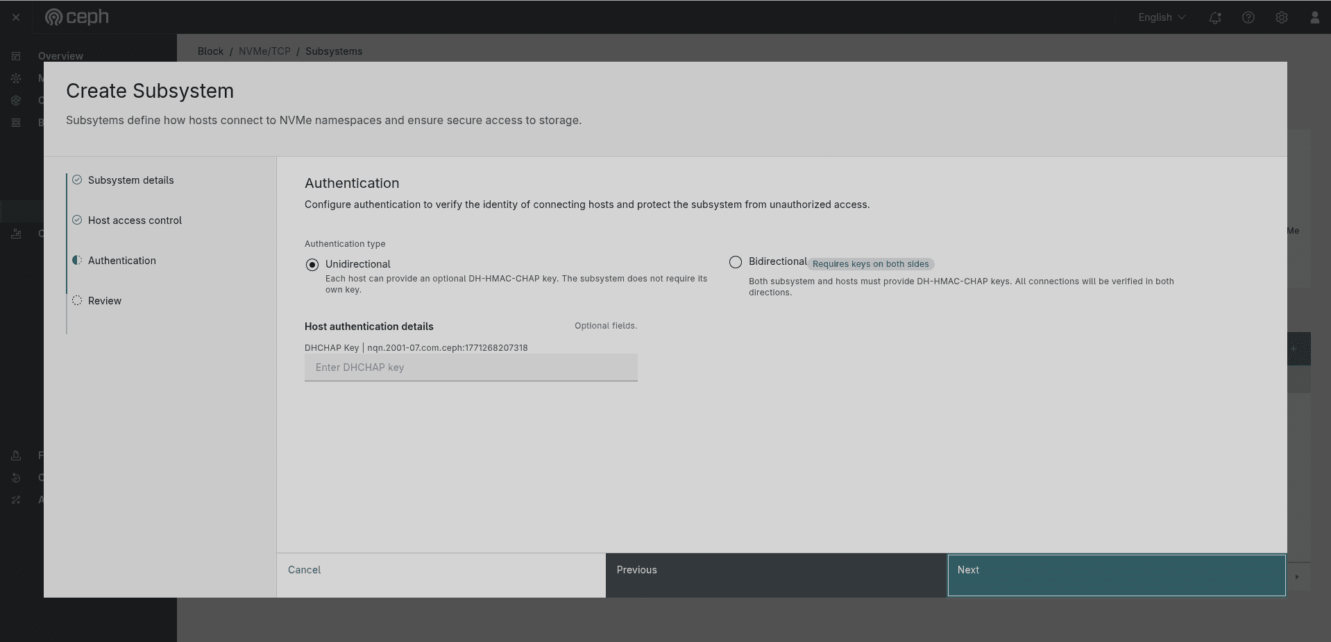 Figure: Create Subsystem wizard — Authentication step with Unidirectional selected (default). Host authentication details show optional DHCHAP Key fields for each added host NQN. Navigation: Cancel / Previous / Next.
Configure authentication between the subsystem and connecting hosts:
- Unidirectional (default) — each host can optionally provide a DH-HMAC-CHAP key. The subsystem does not require its own key. Description: "Each host can provide an optional DH-HMAC-CHAP key. The subsystem does not require its own key."
- Bidirectional (shown with a Requires keys on both sides badge) — both the subsystem and all hosts must provide DH-HMAC-CHAP keys. Description: "Both subsystem and hosts must provide DH-HMAC-CHAP keys. All connections will be verified in both directions."
Bidirectional authentication ¶
Select Bidirectional when you need mutual verification — the subsystem authenticates the host, and the host authenticates the subsystem.
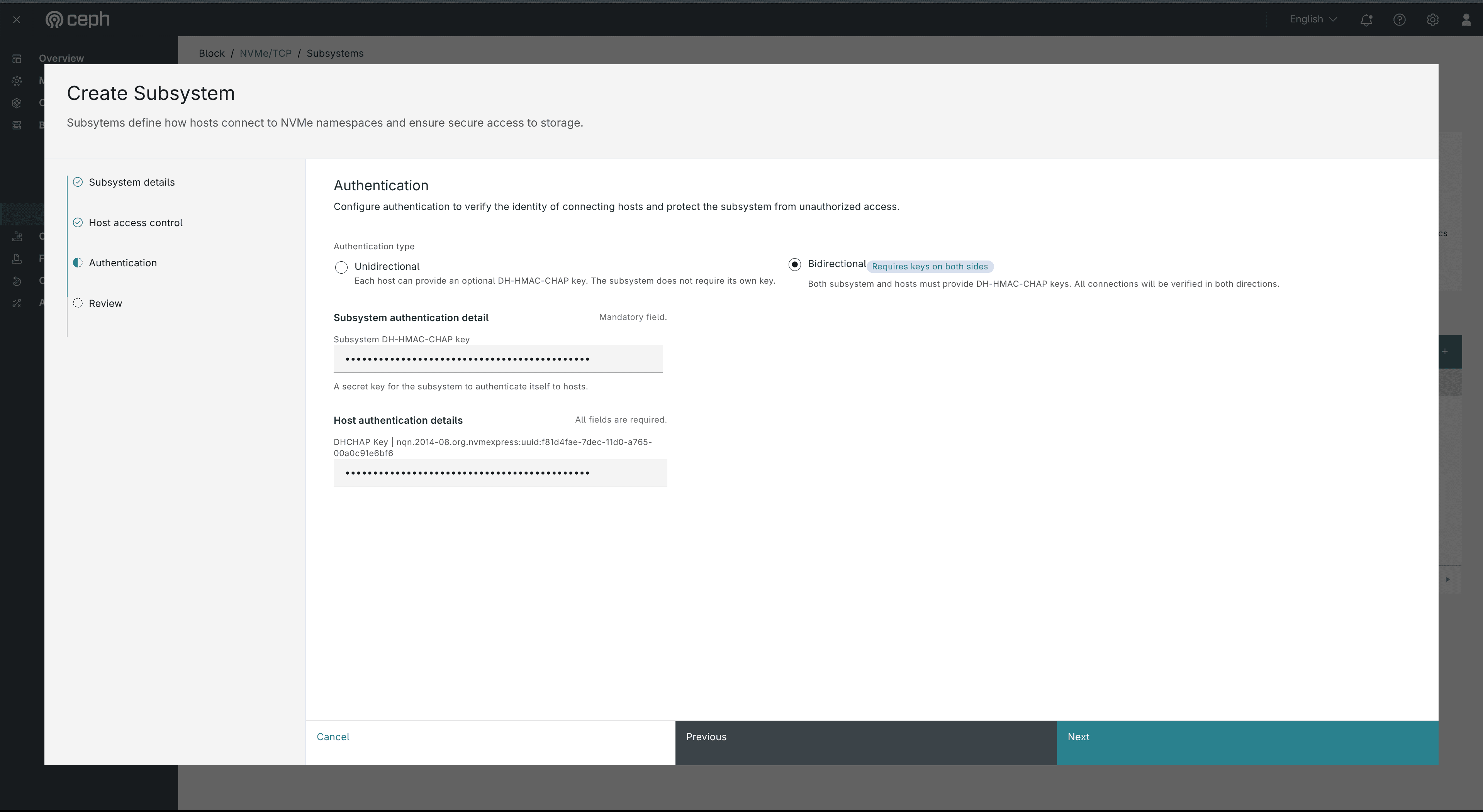 Figure: Create Subsystem wizard — Authentication step with Bidirectional selected (Requires keys on both sides badge). Subsystem authentication detail shows the mandatory Subsystem DH-HMAC-CHAP key field. Host authentication details lists each restricted host NQN with a required DHCHAP Key field (both fields filled / masked). Navigation: Cancel / Previous / Next.
With Bidirectional selected, the form expands:
| Section | What to enter |
|---|---|
| Subsystem authentication detail | Mandatory. Enter a Subsystem DH-HMAC-CHAP key — "A secret key for the subsystem to authenticate itself to hosts." |
| Host authentication details | All fields are required. One DHCHAP Key | <host-NQN> field appears per host added in Step 2 (Restrict to specific hosts). |
Generate valid keys on a host with nvme installed:
nvme gen-dhchap-key
Run the command twice — once for the subsystem key and once for each host key. Keys look like DHHC-1:00:<base64>: (plain Base64 may pass the UI format check but the gateway expects this DHHC format for a successful create).
Prerequisite: the gateway group must have encryption enabled with a valid encryption key. Without it, subsystem details may still create, but adding a host with a DHCHAP key fails (host access control error). Enable encryption when creating or editing the gateway group (see §1.2), wait for gateways to redeploy, then create the subsystem with Bidirectional auth.
With Unidirectional, host DHCHAP fields remain optional — leave blank to skip host-level keys. Click Next to proceed.
Step 4 — Review ¶
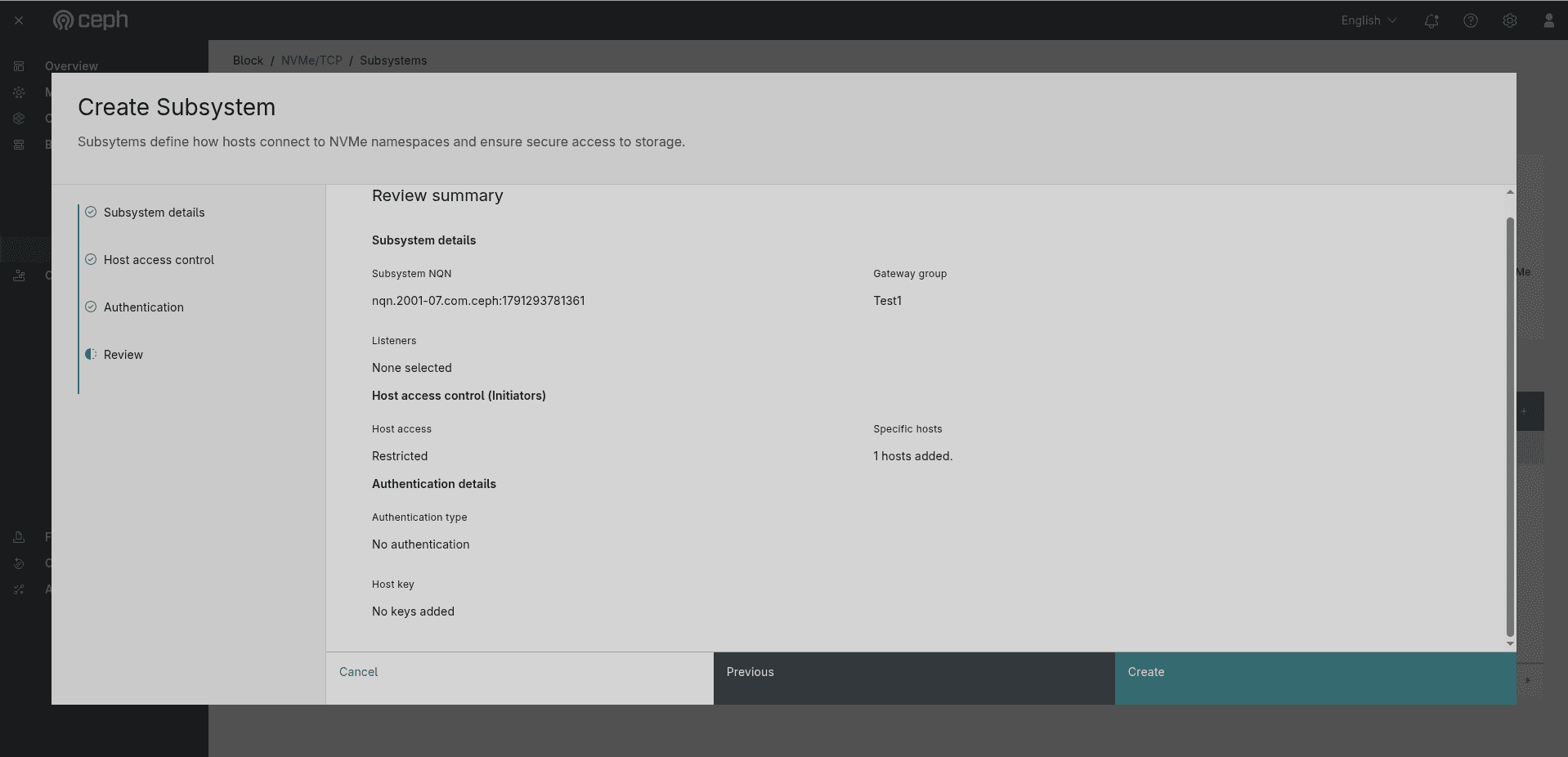 Figure: Create Subsystem wizard — Review step. Shows a full summary: Subsystem NQN, Gateway group (Test1), Listeners (None selected), Host access control (Restricted / 1 hosts added), Authentication details (No authentication / No keys added). Navigation: Cancel / Previous / Create.
The Review summary page displays a read-only summary of all configuration choices before committing:
| Section | Fields shown |
|---|---|
| Subsystem details | Subsystem NQN, Gateway group, Listeners |
| Host access control (Initiators) | Host access (Restricted / Allowed), Specific hosts count |
| Authentication details | Authentication type, Host key status |
Review all values. Click Previous to go back and edit any step, or click Create to create the subsystem.
2.3 The Subsystem List After Creation ¶
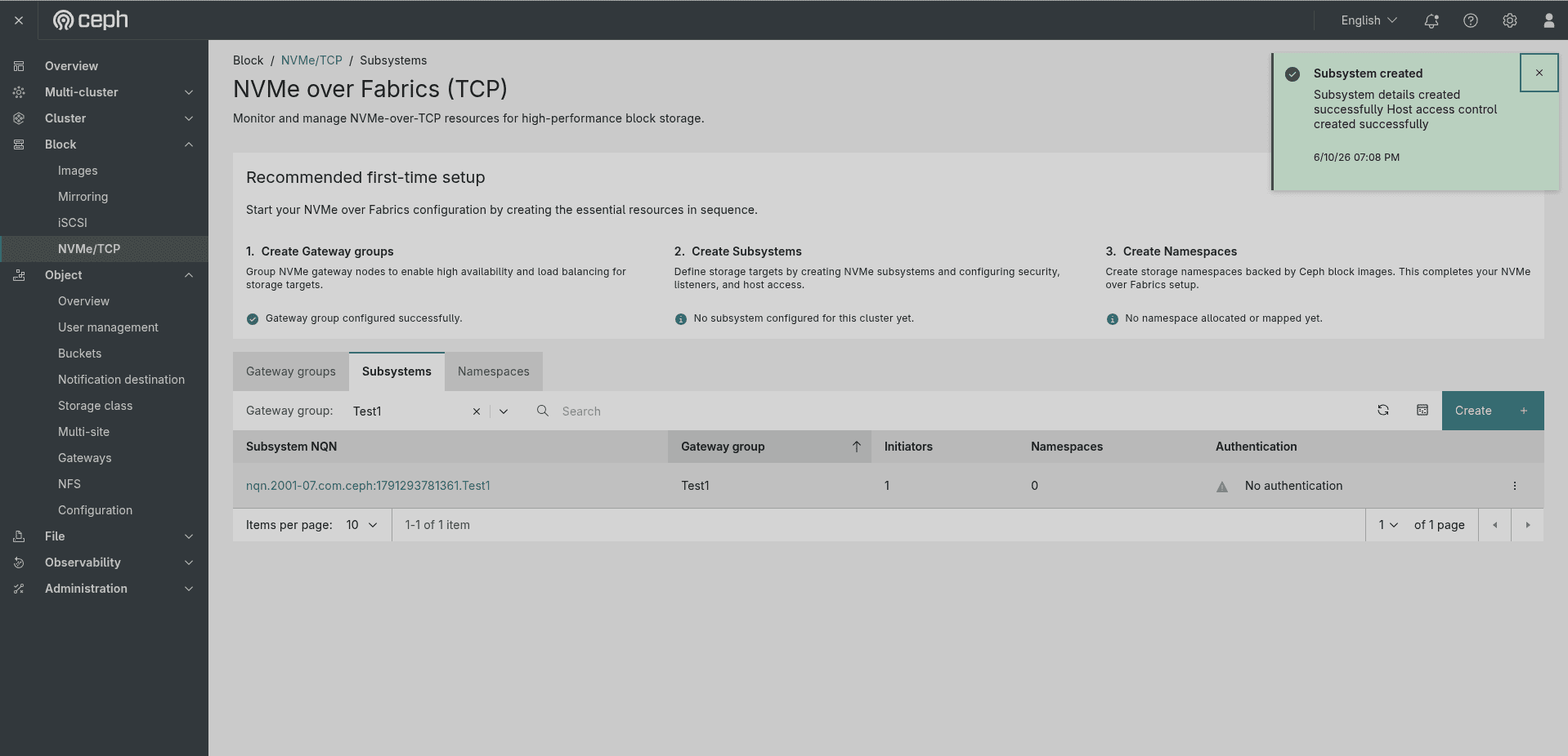 Figure: The Subsystems tab after a subsystem is created — success toast "Subsystem created. Subsystem details created successfully. Host access control created successfully." The list shows
nqn.2001-07.com.ceph:1791293781361.Test1 in gateway group Test1, 1 Initiator, 0 Namespaces, ⚠ No authentication.
After clicking Create, a green success notification appears in the top-right corner:
"Subsystem created — Subsystem details created successfully. Host access control created successfully." (6/10/26 07:08 PM)
The new subsystem appears in the table. Note the ⚠ orange warning icon next to No authentication — this is a reminder that enabling authentication is recommended for production environments.
2.4 Subsystem Detail View ¶
Clicking the subsystem NQN (e.g., nqn.2001-07.com.ceph:1791293781361.Test1) opens its detail view. The left sidebar shows five tabs: Overview, Initiators, Namespaces, Listeners, and Performance.
Overview Tab ¶
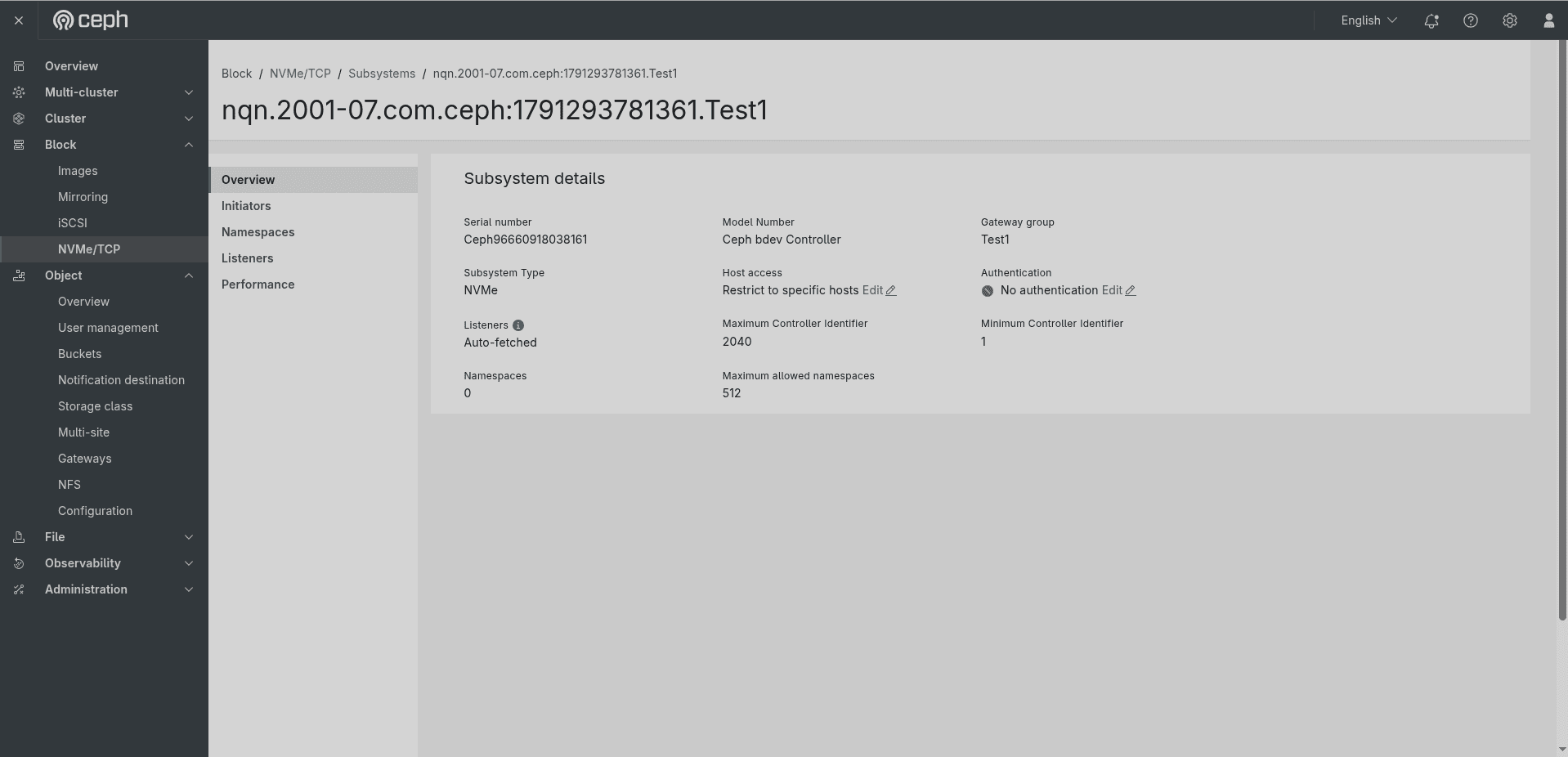 Figure: Subsystem detail view — Overview tab showing Subsystem details: Serial number (Ceph96660918038161), Model Number (Ceph bdev Controller), Gateway group (Test1), Subsystem Type (NVMe), Host access (Restrict to specific hosts — Edit link), Authentication (🔴 No authentication — Edit link), Listeners (Auto-fetched ℹ), Maximum Controller Identifier (2040), Minimum Controller Identifier (1), Namespaces (0), Maximum allowed namespaces (512).
The Subsystem details panel contains:
| Property | Value / Description |
|---|---|
| Serial number | Auto-generated serial (e.g., Ceph96660918038161). |
| Model Number | Always Ceph bdev Controller. |
| Gateway group | The gateway group this subsystem belongs to (e.g., Test1). |
| Subsystem Type | Always NVMe. |
| Host access | Current host access mode (e.g., Restrict to specific hosts) with an inline Edit link. |
| Authentication | Current auth mode — 🔴 No authentication, or ✅ Bi-directional / unidirectional — with an inline Edit link. |
| Listeners | How listeners are configured — Auto-fetched or Manually selected, with an info icon ℹ. |
| Maximum Controller Identifier | 2040 |
| Minimum Controller Identifier | 1 |
| Namespaces | Current namespace count (e.g., 0). |
| Maximum allowed namespaces | 512 |
After a successful Bidirectional create, Overview shows authentication as Bi-directional:
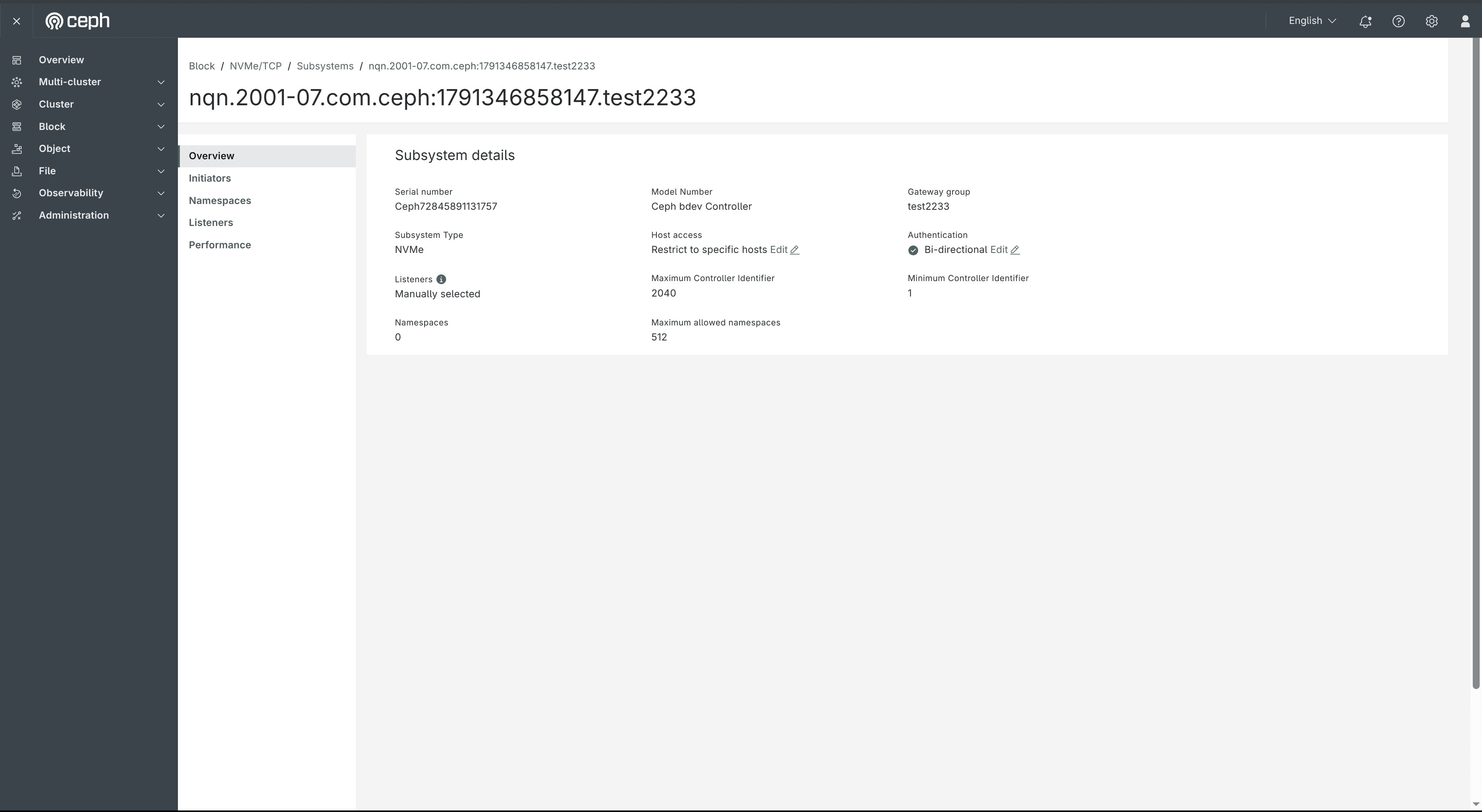 Figure: Subsystem Overview for
nqn.2001-07.com.ceph:1791346858147.test2233 in gateway group test2233 — Host access: Restrict to specific hosts (Edit), Authentication: ✅ Bi-directional (Edit), Listeners: Manually selected.
Edit Authentication ¶
Click Edit next to Authentication on the Overview tab to open the Edit authentication dialog. You can change the authentication type and keys without recreating the subsystem.
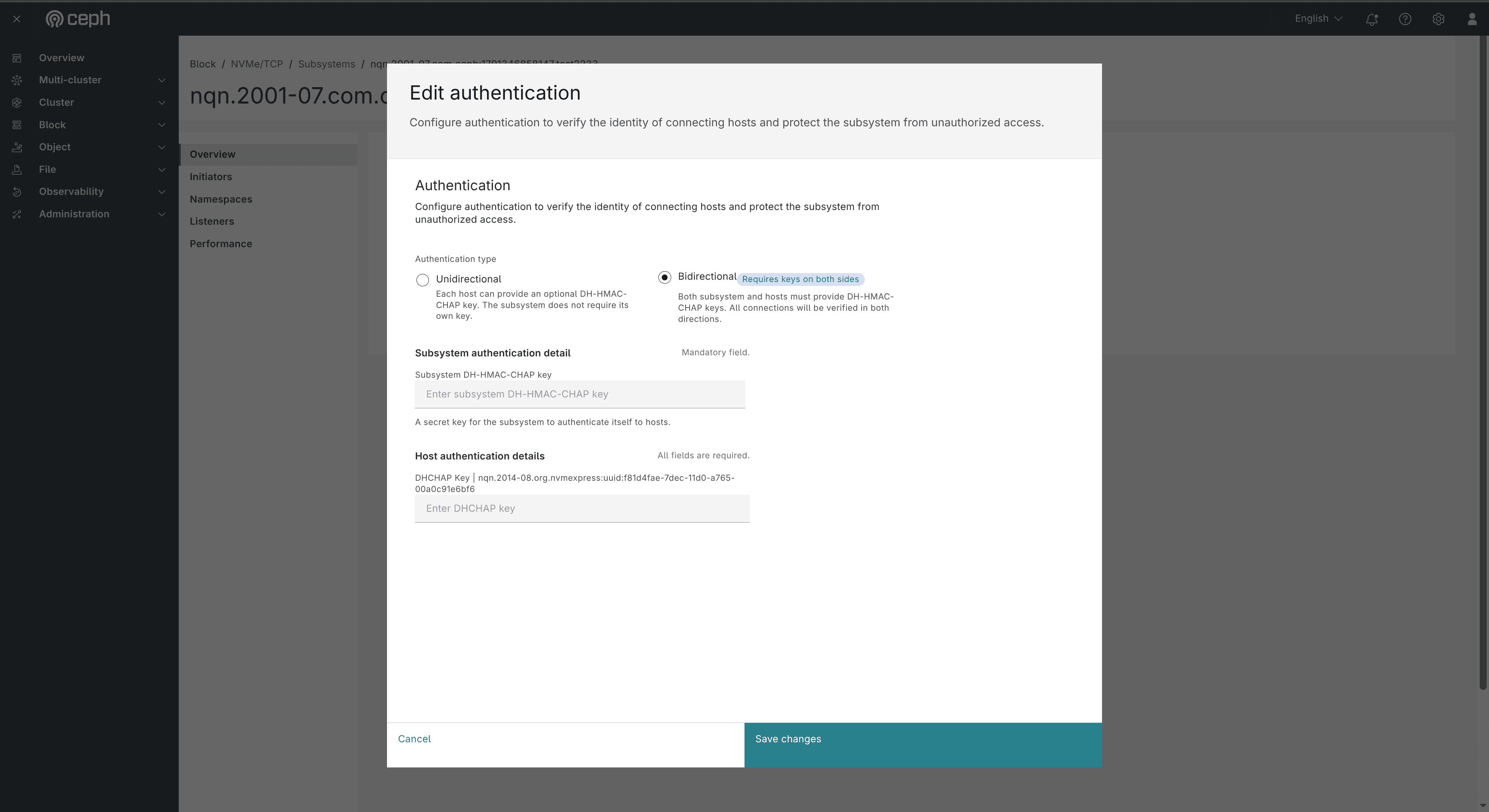 Figure: Edit authentication dialog — Authentication type Bidirectional selected (Requires keys on both sides badge). Subsystem authentication detail (mandatory Subsystem DH-HMAC-CHAP key). Host authentication details with a required DHCHAP Key field per host NQN. Buttons: Cancel / Save changes.
The form matches Create Subsystem → Authentication (Step 3):
- Unidirectional — optional per-host DH-HMAC-CHAP keys; no subsystem key required.
- Bidirectional — mandatory Subsystem DH-HMAC-CHAP key plus required host DHCHAP keys for every restricted initiator.
Enter or update keys (use nvme gen-dhchap-key for valid DHHC-1:… values), then click Save changes. Click Cancel to discard.
Note: Switching from Bidirectional to Unidirectional shows a warning that the subsystem DHCHAP key will be deleted permanently, which can expose the subsystem to unauthorised access. Confirm carefully before saving.
To change which hosts are allowed (allow-all vs restricted NQNs), use Edit next to Host access (opens the Add Initiator flow) or manage rows on the Initiators tab (including Edit host key for a single initiator).
Initiators Tab ¶
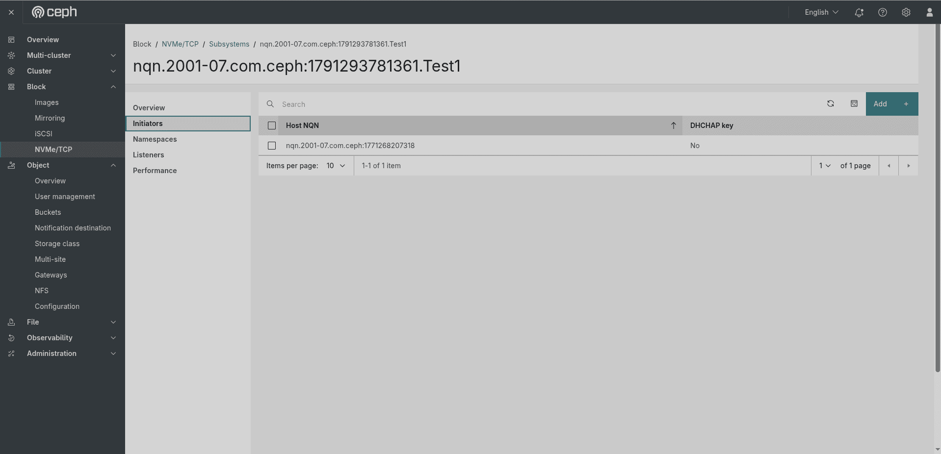 Figure: Subsystem Initiators tab — table with columns Host NQN and DHCHAP key. One row:
nqn.2001-07.com.ceph:1771268207318, DHCHAP key: No. Action bar at top: 1 item selected — Edit host key | Remove | Cancel buttons.
The Initiators tab lists all host NQNs permitted to connect to this subsystem. The table columns are:
| Column | Description |
|---|---|
| Host NQN | The NVMe Qualified Name of the initiator host. |
| DHCHAP key | Whether a DH-HMAC-CHAP key is configured for this host — No if none is set. |
When one or more rows are selected (checkbox), a teal action bar appears at the top with three actions: Edit host key, Remove, and Cancel.
Adding an initiator after subsystem creation is done via a dedicated Add Initiator wizard accessible from the Initiators tab. The wizard has two steps: Host access control and Authentication (optional).
Add Initiator — Step 1: Host Access Control ¶
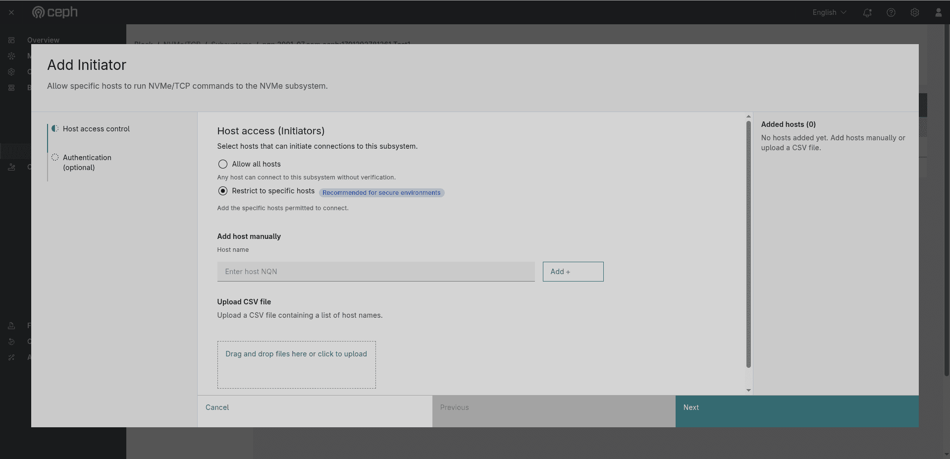 Figure: Add Initiator wizard — Host access control step. Options: Allow all hosts / Restrict to specific hosts (Recommended badge, selected). Add host manually field (Enter host NQN + Add + button). Upload CSV file drop zone. Right panel: Added hosts (0).
The Add Initiator form is identical to the subsystem creation Host access control step:
- Allow all hosts — grants access to every initiator on the network. Note: authentication is not supported in this mode.
- Restrict to specific hosts (recommended) — add NQNs manually via the Host name field + Add + button, or upload a CSV file.
Click Next to proceed to the optional Authentication step.
Add Initiator — Step 2: Authentication (Optional) ¶
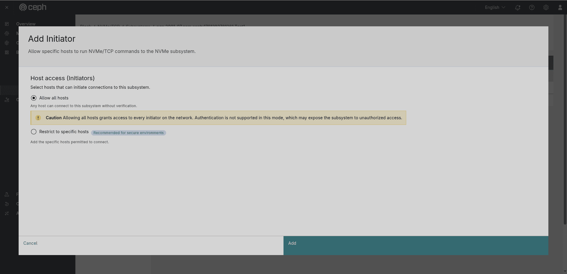 Figure: Add Initiator wizard — Authentication (optional) step. Authentication type: Unidirectional (selected) / Bidirectional. Host authentication details showing DHCHAP Key field for the host NQN. Navigation: Cancel / Previous / Next.
Configure the DH-HMAC-CHAP key for the new host (same as the Authentication step in the Create Subsystem wizard). Click Next to complete adding the initiator.
Editing a host key — select a host row and click Edit host key in the action bar. This opens the Edit Host Key dialog.
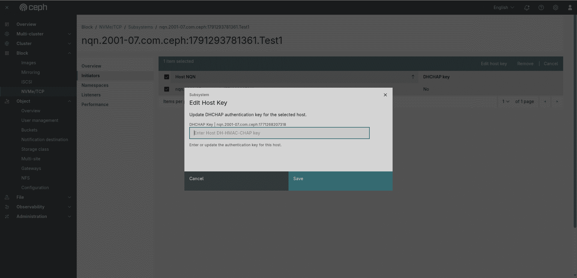 Figure: The Edit Host Key dialog for subsystem
nqn.2001-07.com.ceph:1791293781361.Test1 — subtitle "Update DHCHAP authentication key for the selected host." Field: DHCHAP Key | nqn.2001-07.com.ceph:1771268207318 with placeholder "Enter Host DH-HMAC-CHAP key" and hint "Enter or update the authentication key for this host." Buttons: Cancel / Save.
The dialog is titled "Edit Host Key" with subtitle "Update DHCHAP authentication key for the selected host." Enter the new DH-HMAC-CHAP key in the text field and click Save, or Cancel to discard.
Removing a specific host — select the host row and click Remove in the action bar. A Remove host — Confirm remove dialog appears.
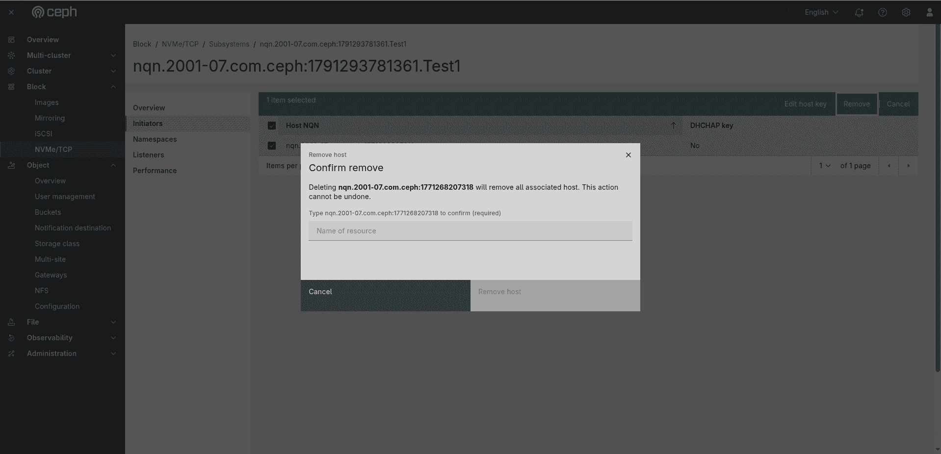 Figure: The Remove host — Confirm remove dialog — warning "Deleting nqn.2001-07.com.ceph:1771268207318 will remove all associated host. This action cannot be undone." Text-confirmation field "Type nqn.2001-07.com.ceph:1771268207318 to confirm (required)". Buttons: Cancel / Remove host (greyed until confirmed).
The dialog warns: "Deleting nqn.2001-07.com.ceph:1771268207318 will remove all associated host. This action cannot be undone." Type the full NQN into the confirmation field to activate the Remove host button.
Removing the "Allow any host" entry — when the subsystem is in Allow all hosts mode, the Initiators tab shows an Allow any host(*) row. A warning banner reads:
⚠ All hosts allowed — "Allowing all hosts grants access to every initiator on the network. Authentication is not supported in this mode, which may expose the subsystem to unauthorized access."
Selecting that row and clicking Remove opens the Remove host — Confirm remove dialog for Allow any host(*).
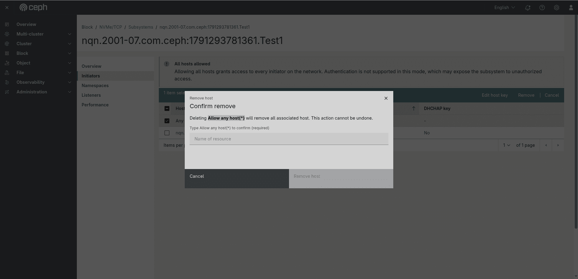 Figure: The Initiators tab with the All hosts allowed warning banner visible, and the Remove host Confirm remove dialog open for Allow any host(*) — text-confirmation field requires typing
Allow any host(*) to activate the Remove host button.
Listeners Tab ¶
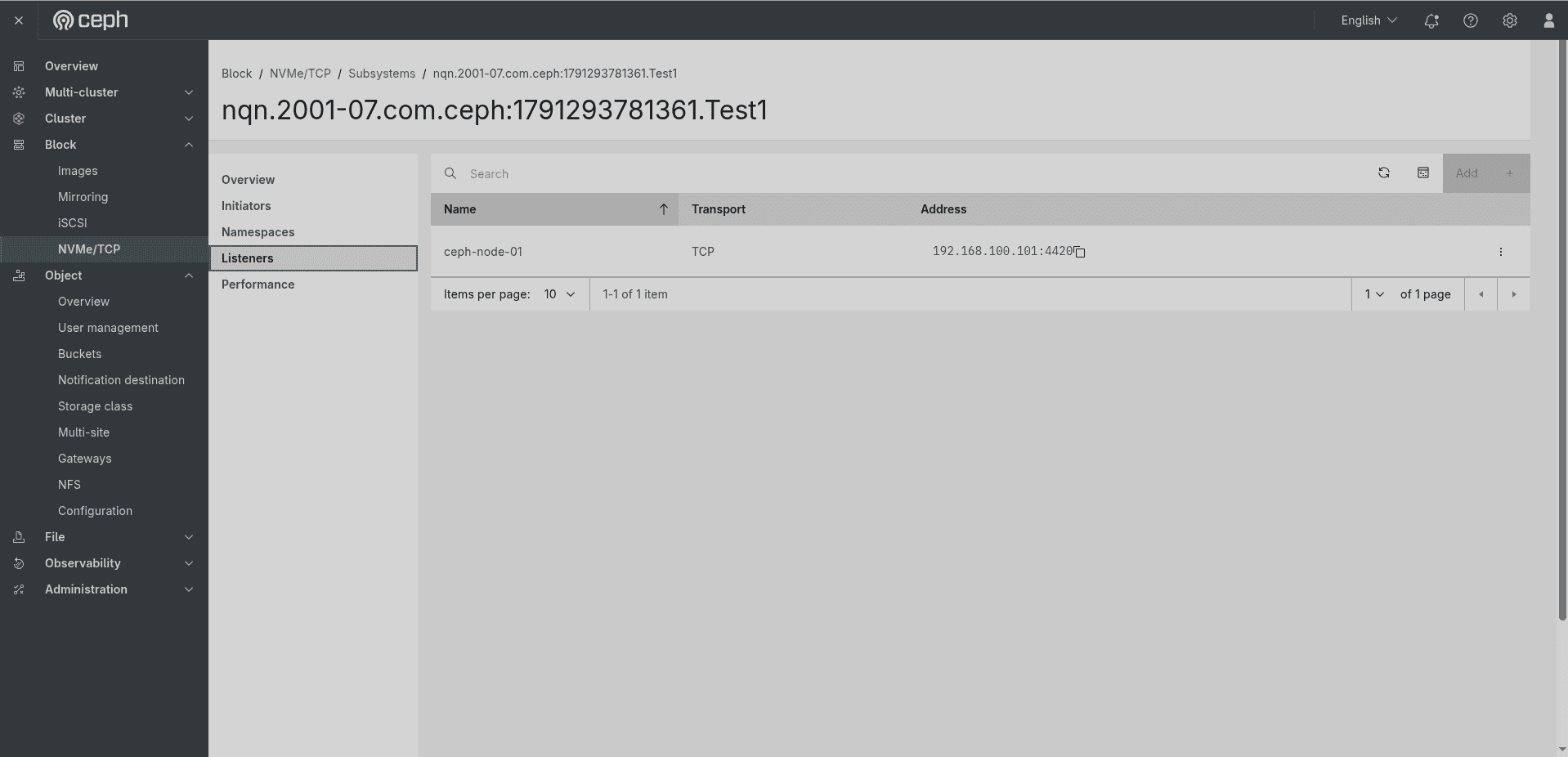 Figure: Subsystem Listeners tab — table with columns Name, Transport, Address. One row:
ceph-node-01, TCP, 192.168.100.101:4420. Top-right: Add button.
The Listeners tab shows the network endpoints where this subsystem accepts NVMe/TCP connections. The table columns are:
| Column | Description |
|---|---|
| Name | The gateway node hostname serving as the listener (e.g., ceph-node-01). |
| Transport | The transport protocol — always TCP for NVMe/TCP. |
| Address | The IP address and port the listener binds to (e.g., 192.168.100.101:4420). The copy icon allows copying the address. |
The Add button in the top-right corner opens a form to manually add a listener when Add manually was selected during subsystem creation.
Namespaces Tab (within Subsystem) ¶
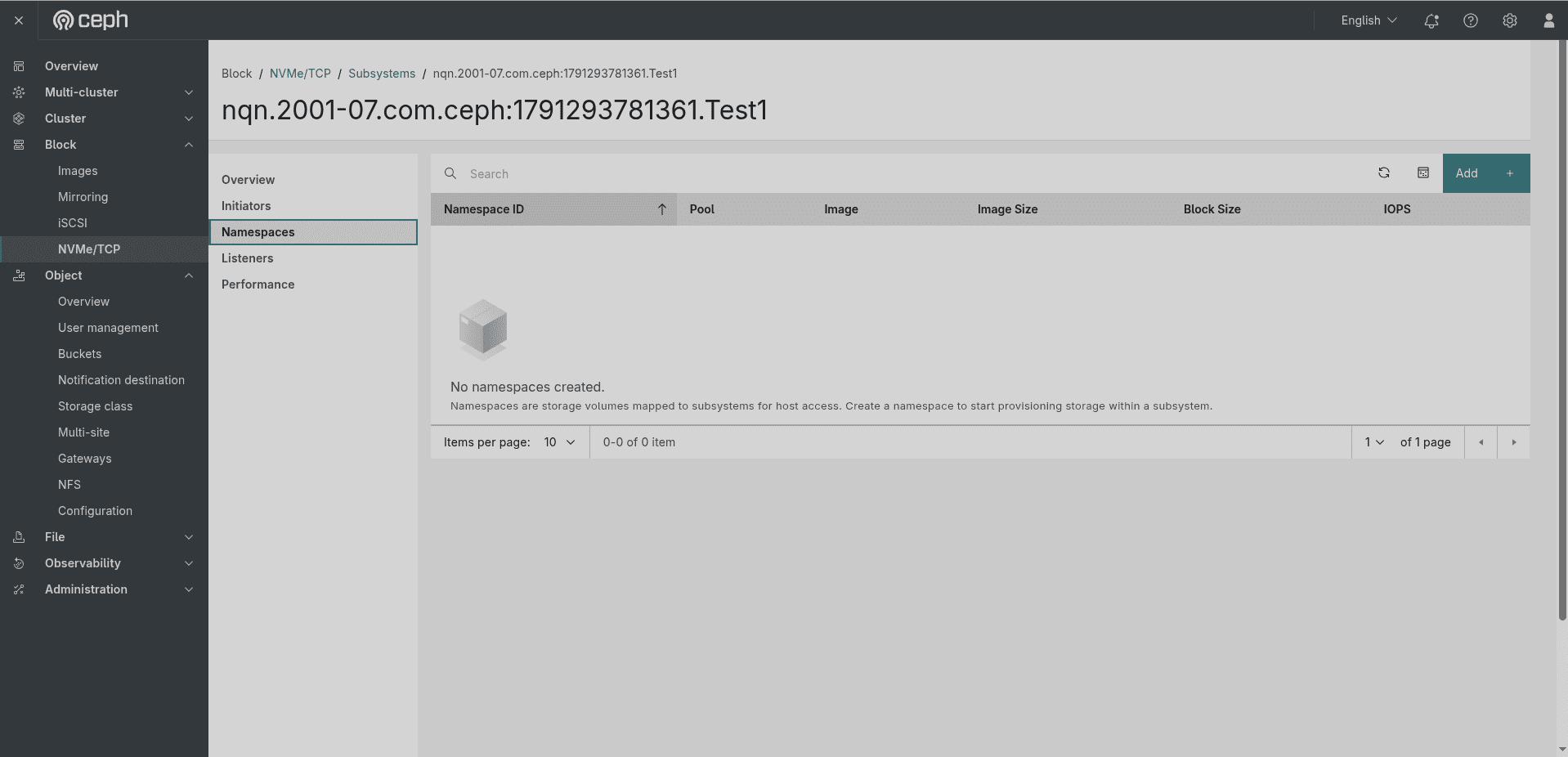 Figure: Subsystem Namespaces tab — empty state: "No namespaces created. Namespaces are storage volumes mapped to subsystems for host access." Columns: Namespace ID, Pool, Image, Image Size, Block Size, IOPS. Top-right: Add button.
The Namespaces tab within the subsystem detail view shows all namespaces attached to this specific subsystem. The table columns are:
| Column | Description |
|---|---|
| Namespace ID | The numeric NSID within this subsystem. |
| Pool | The RADOS pool containing the backing RBD image. |
| Image | The RBD image name. |
| Image Size | The size of the backing image. |
| Block Size | The logical block size exposed to the host. |
| IOPS | Real-time I/O operations per second for this namespace. |
Click Add to create a namespace directly from within the subsystem context.
Performance Tab ¶
The Performance tab embeds the Grafana NVMe-oF Gateways Performance dashboard for the selected subsystem. Use it to monitor gateway CPU, I/O latency, IOPS, and throughput without leaving the Dashboard.
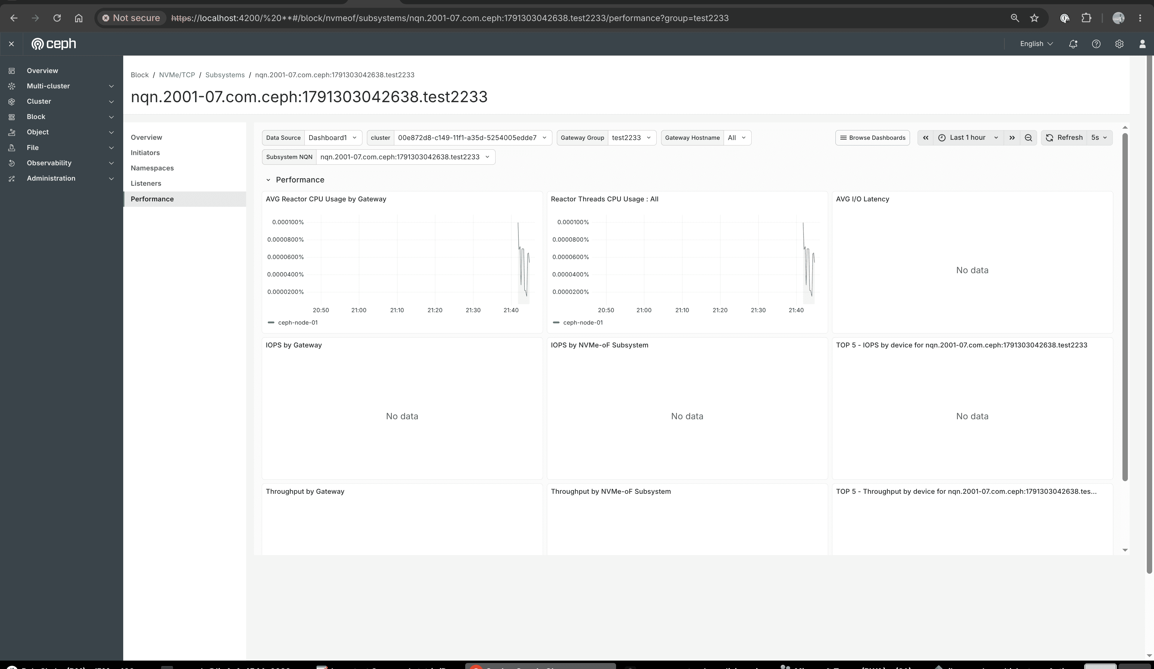 Figure: Subsystem Performance tab for
nqn.2001-07.com.ceph:1791303042638.test2233 — Grafana filters (Data Source, Cluster, Gateway Group test2233, Gateway Hostname, Subsystem NQN), time range Last 1 hour, refresh 5s. Panels include AVG Reactor CPU Usage by Gateway, Reactor Threads CPU Usage, AVG I/O Latency, IOPS / Throughput by Gateway and by Subsystem, and TOP 5 device charts. Some panels show No data until the subsystem is under I/O load.
Prerequisites
- Cluster monitoring (Prometheus + Grafana) must be enabled and the Dashboard Grafana URL configured under Cluster → Manager modules → dashboard (or your site’s monitoring setup).
- Your user needs Grafana read permission. Without it, the tab shows that Grafana permissions are required to view performance details.
Filters and controls (top of the embedded dashboard):
| Control | Purpose |
|---|---|
| Data Source | Grafana data source (typically Dashboard). |
| Cluster | Ceph cluster FSID used by the metrics. |
| Gateway Group | Pre-filled with the current gateway group (e.g., test2233). |
| Gateway Hostname | Limit charts to one gateway, or All. |
| Subsystem NQN | Pre-filled with the subsystem you opened. |
| Time range | Window for metrics (e.g., Last 1 hour). |
| Refresh | Auto-refresh interval (e.g., 5s). |
Typical panels
| Panel | What it shows |
|---|---|
| AVG Reactor CPU Usage by Gateway | Average SPDK reactor CPU per gateway host. |
| Reactor Threads CPU Usage | Per-reactor-thread CPU usage. |
| AVG I/O Latency | Average I/O latency for the subsystem. |
| IOPS by Gateway / by NVMe-oF Subsystem | I/O operations per second, by gateway or subsystem. |
| TOP 5 — IOPS by device | Highest-IOPS devices for this subsystem NQN. |
| Throughput by Gateway / by Subsystem | Bandwidth (read/write) by gateway or subsystem. |
| TOP 5 — Throughput by device | Highest-throughput devices for this subsystem NQN. |
Note: Empty panels (No data) are normal when no clients are connected or no I/O is running. Generate load against a connected namespace to populate latency, IOPS, and throughput charts. CPU panels may still show low baseline activity from the gateway processes.
2.5 Deleting a Subsystem ¶
To delete a subsystem, go to Block → NVMe/TCP → Subsystems, select the subsystem row, and choose Delete from the action menu (or the table actions bar). A Confirm delete dialog opens.
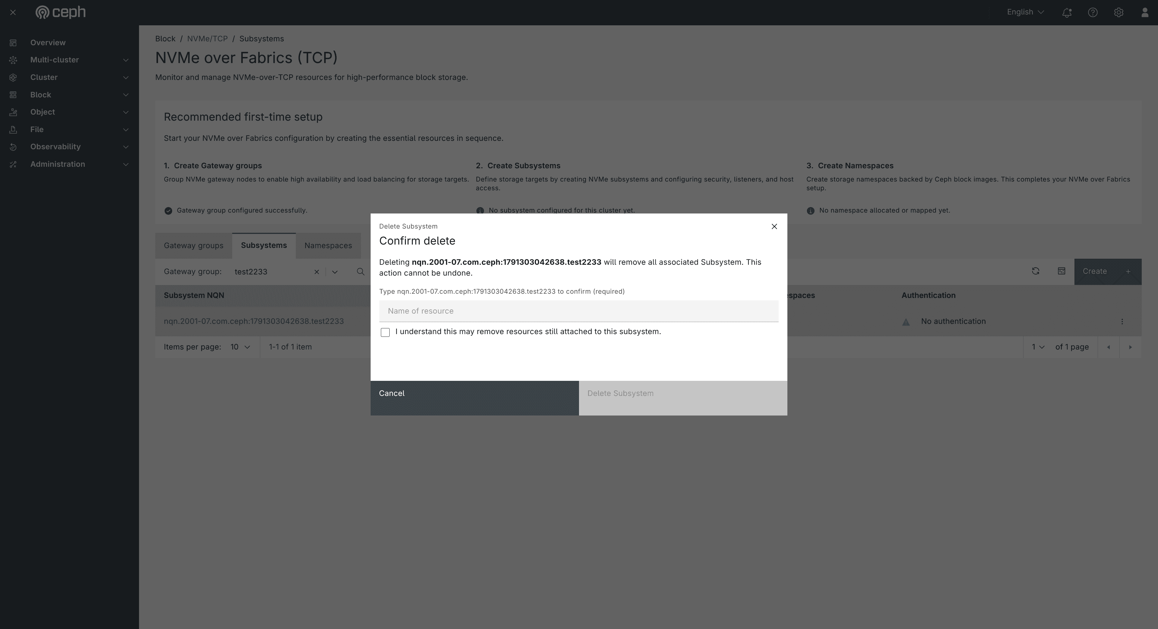 Figure: Confirm delete dialog for
nqn.2001-07.com.ceph:1791303042638.test2233 — warning that the action cannot be undone, empty Name of resource field, unchecked acknowledgement checkbox, and a greyed-out Delete Subsystem button.
The dialog warns: "Deleting nqn.2001-07.com.ceph:1791303042638.test2233 will remove all associated Subsystem. This action cannot be undone."
Before the destructive button activates you must:
- Type the exact subsystem NQN into the Name of resource field.
- Check I understand this may remove resources still attached to this subsystem.
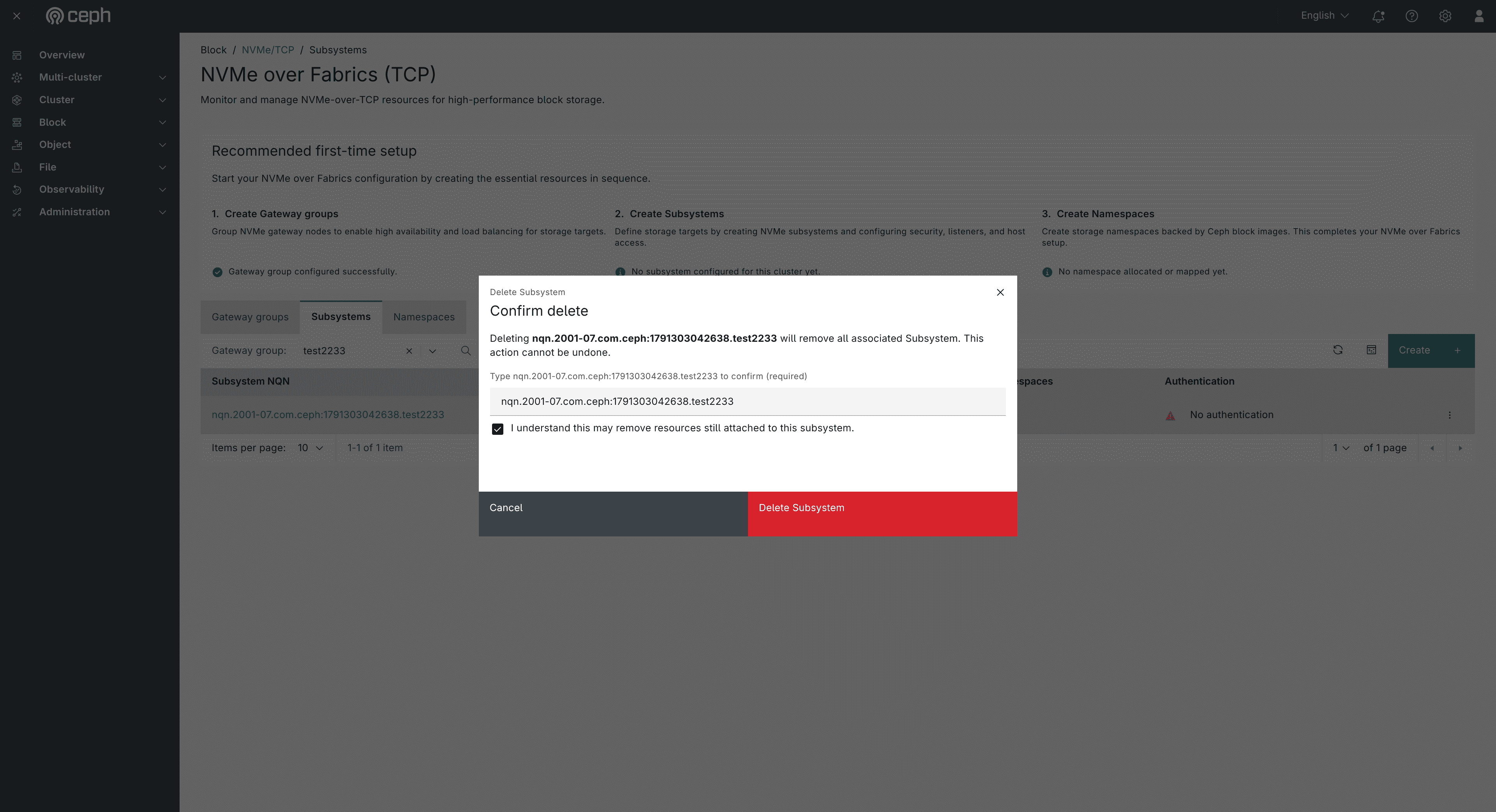 Figure: Same dialog after the full NQN is typed and the acknowledgement checkbox is checked — the red Delete Subsystem button is enabled.
Click Delete Subsystem to remove it, or Cancel to abort.
Note: Prefer deleting namespaces (and clearing host access) first when possible. The acknowledgement checkbox exists because deleting a subsystem can also remove resources that are still attached to it.
3. Namespaces ¶
After creating subsystems, the final step is to create Namespaces — storage volumes backed by Ceph RBD images that are mapped to a subsystem and made accessible to initiator hosts over NVMe/TCP.
3.1 The Namespaces Tab — Empty State ¶
Navigate to the Namespaces tab on the NVMe/TCP landing page.
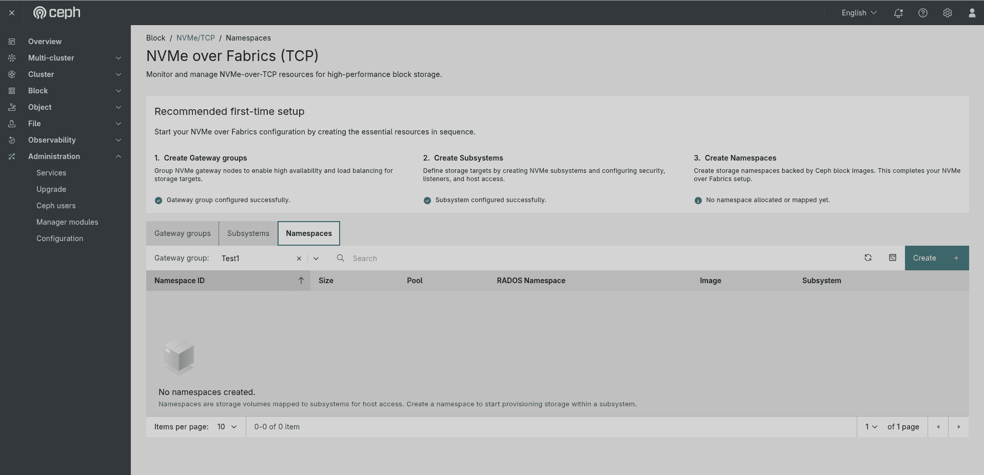 Figure: The Block → NVMe/TCP → Namespaces tab with Gateway group: Test1 — all three setup steps complete (Gateway group ✅, Subsystem ✅, Namespaces ℹ "No namespace allocated or mapped yet"). Empty state: "No namespaces created." Columns: Namespace ID, Size, Pool, RADOS Namespace, Image, Subsystem.
At this point the banner shows that steps 1 and 2 are complete (✅) while step 3 is still pending (ℹ). The empty-state message reads: "No namespaces created. Namespaces are storage volumes mapped to subsystems for host access. Create a namespace to start provisioning storage within a subsystem."
3.2 Creating a Namespace ¶
Click Create on the Namespaces tab. This opens the Create Namespace page — breadcrumb: Block / NVMe/TCP / Namespaces / Create. The subtitle reads "Namespaces define the storage volumes that subsystems present to hosts."
Step 1 — Namespace Configuration ¶
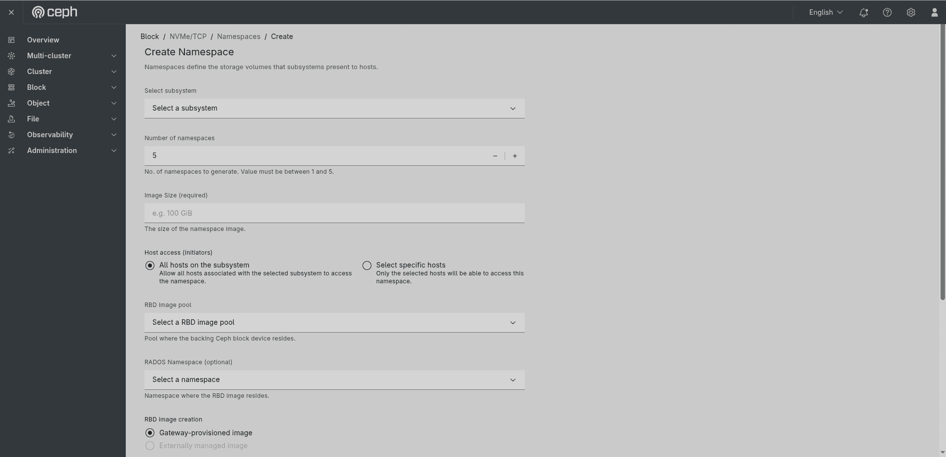 Figure: The Create Namespace form — fields: Select subsystem (dropdown), Number of namespaces (spinner, default 5, hint: "No. of namespaces to generate. Value must be between 1 and 5."), Image Size (required, e.g. 100 GiB), Host access (All hosts on the subsystem / Select specific hosts), RBD image pool (dropdown), RADOS Namespace (optional dropdown), RBD image creation (Gateway-provisioned image / Externally managed image radio).
Fill in the following fields:
- Select subsystem — choose the subsystem NQN this namespace will be attached to (dropdown).
- Number of namespaces — how many namespaces to create in one operation. The hint reads "No. of namespaces to generate. Value must be between 1 and 5." Default is
5; use the − / + spinner to adjust. - Image Size (required) — the size of each backing RBD image (e.g.,
100 GiB). The hint reads "The size of the namespace image." - Host access (Initiators) — choose who can access this namespace:
- All hosts on the subsystem (default) — "Allow all hosts associated with the selected subsystem to access the namespace."
- Select specific hosts — "Only the selected hosts will be able to access this namespace."
- RBD image pool — the RADOS pool where the backing RBD image resides. The hint reads "Pool where the backing Ceph block device resides."
- RADOS Namespace (optional) — the RADOS namespace within the pool. The hint reads "Namespace where the RBD image resides."
- RBD image creation — choose how the backing image is managed:
- Gateway-provisioned image (default) — the gateway creates and manages the RBD image automatically.
- Externally managed image (greyed out when bulk creation is selected) — use a pre-existing RBD image.
Step 2 — Image Name, Block Size and Create ¶
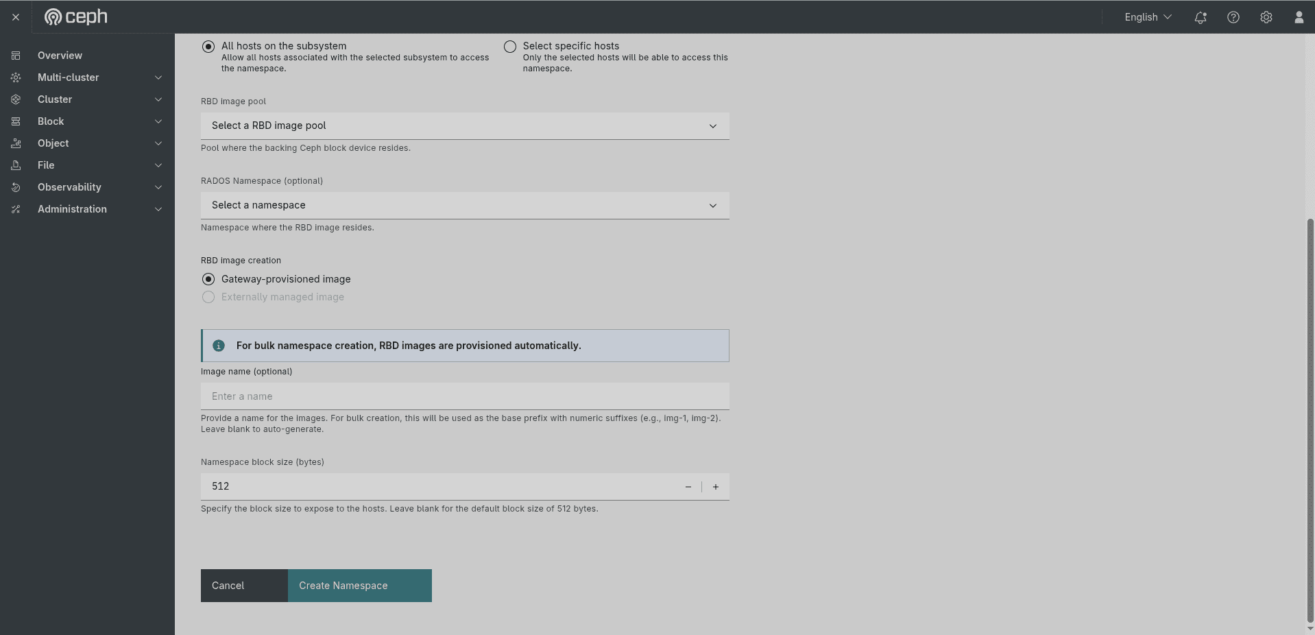 Figure: Create Namespace form scrolled down — Host access radio (All hosts on subsystem selected), RBD image pool dropdown, RADOS Namespace dropdown, RBD image creation (Gateway-provisioned selected), blue info banner "For bulk namespace creation, RBD images are provisioned automatically.", Image name (optional, hint: base prefix with numeric suffixes), Namespace block size (bytes) spinner (default 512, hint: "Specify the block size to expose to the hosts. Leave blank for the default block size of 512 bytes."), Cancel / Create Namespace buttons.
The form continues with:
- RBD image creation info banner — when Gateway-provisioned image is selected and more than one namespace is requested, a blue info banner reads: "For bulk namespace creation, RBD images are provisioned automatically."
- Image name (optional) — a base name for the RBD images. The hint reads "Provide a name for the images. For bulk creation, this will be used as the base prefix with numeric suffixes (e.g., img-1, img-2). Leave blank to auto-generate."
- Namespace block size (bytes) — the logical block size exposed to hosts, default
512. The hint reads "Specify the block size to expose to the hosts. Leave blank for the default block size of 512 bytes." Use the − / + spinner to adjust.
Click Create Namespace to create the namespace(s), or Cancel to discard.
3.3 The Namespaces Tab — After Creation ¶
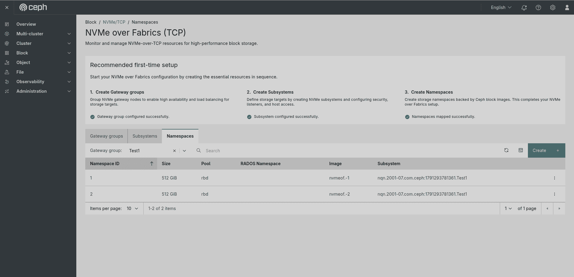 Figure: The Block → NVMe/TCP → Namespaces tab after creation — all three setup steps show ✅ (Gateway group configured, Subsystem configured, Namespaces mapped successfully). Two namespaces listed: ID 1 (512 GiB, pool
rbd, image nvmeof.-1, subsystem nqn.2001-07.com.ceph:1791293781361.Test1) and ID 2 (512 GiB, pool rbd, image nvmeof.-2, same subsystem). Each row has a ⋮ action menu.
Once namespaces are created, all three setup-sequence steps show ✅. The table columns are:
| Column | Description |
|---|---|
| Namespace ID | The numeric NSID within the subsystem (e.g., 1, 2). |
| Size | The size of the backing RBD image (e.g., 512 GiB). |
| Pool | The RADOS pool containing the RBD image (e.g., rbd). |
| RADOS Namespace | The RADOS namespace within the pool (blank if the default namespace). |
| Image | The RBD image name (e.g., nvmeof.-1, nvmeof.-2). |
| Subsystem | The subsystem NQN this namespace is attached to. |
The ⋮ action menu on each row provides Expand and Delete options.
3.4 Expanding a Namespace ¶
To increase a namespace's storage capacity, click the ⋮ action menu on the namespace row and select Expand. This opens the Expand namespace dialog.
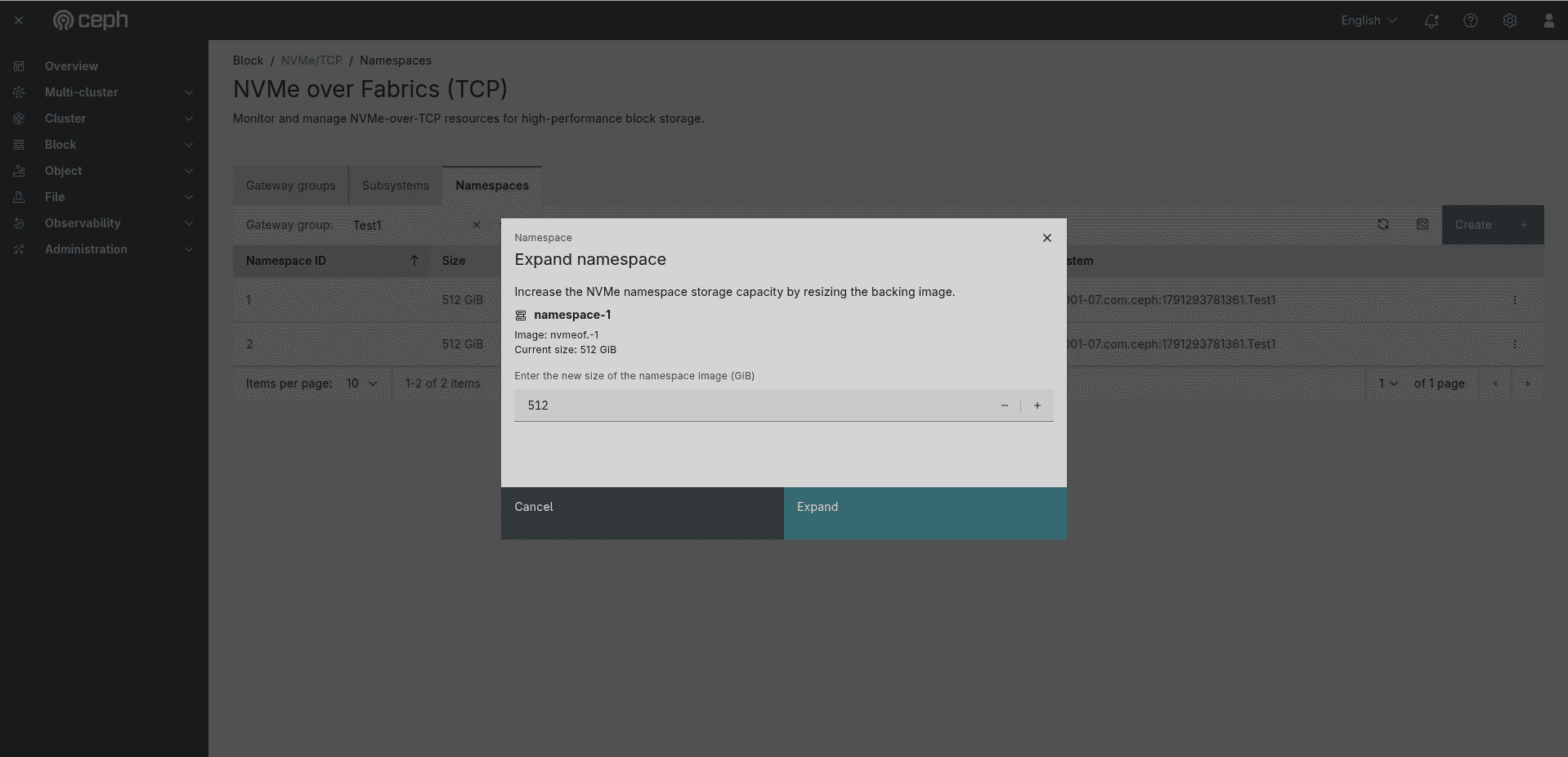 Figure: The Expand namespace dialog for
namespace-1 — subtitle "Increase the NVMe namespace storage capacity by resizing the backing image." Shows Image: nvmeof.-1, Current size: 512 GiB. Field: "Enter the new size of the namespace image (GiB)" spinner pre-filled with 512. Buttons: Cancel / Expand.
The dialog shows:
- Namespace name — the namespace identifier (e.g.,
namespace-1). - Image — the backing RBD image (e.g.,
nvmeof.-1). - Current size — the existing capacity (e.g.,
512 GiB). - New size field — enter the new size in GiB using the − / + spinner. The new value must be greater than the current size (namespaces can only be expanded, not shrunk).
Click Expand to resize, or Cancel to discard.
3.5 Deleting a Namespace ¶
To delete a namespace, click the ⋮ action menu and select Delete. A Delete Namespace — Confirm delete dialog appears.
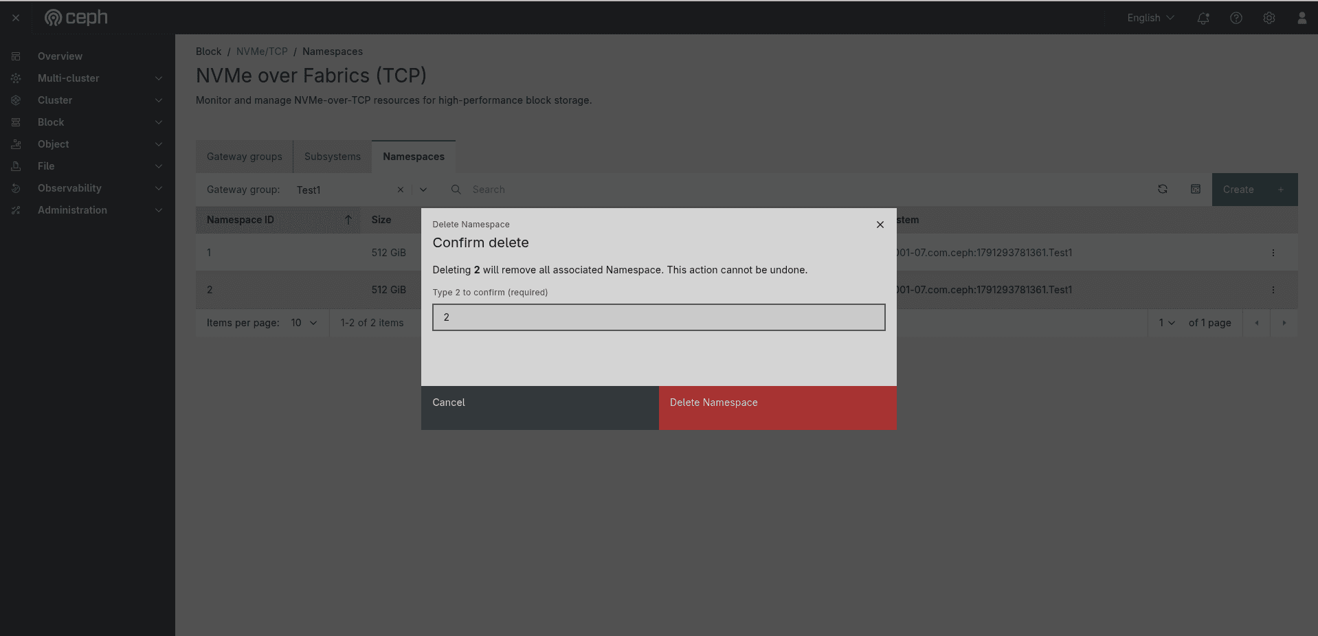 Figure: The Delete Namespace — Confirm delete dialog for namespace ID 2 — warning "Deleting 2 will remove all associated Namespace. This action cannot be undone." Text-confirmation field pre-filled with
2 (required). Red Delete Namespace button active once the ID is typed. Buttons: Cancel / Delete Namespace.
The dialog reads: "Deleting 2 will remove all associated Namespace. This action cannot be undone." Type the namespace ID into the confirmation field to activate the red Delete Namespace button.
Key Features of the Dashboard for NVMe/TCP Management ¶
1. Guided Three-Step Setup Sequence ¶
The Recommended first-time setup banner tracks all three steps (Gateway groups → Subsystems → Namespaces) with live ✅ / ℹ status indicators, so operators always know exactly where they are in the configuration flow.
2. Flexible Certificate Management ¶
When enabling mTLS, the Dashboard offers Internal (Cephadm CA auto-generates certificates with optional Custom SAN Entries) and External (upload Root CA, client cert/key, server cert/key) modes — covering both development and enterprise PKI environments.
3. Four-Step Subsystem Creation Wizard ¶
The Create Subsystem wizard guides through Subsystem details → Host access control → Authentication → Review, with the full configuration visible in a Review summary before committing. This prevents misconfiguration and makes all choices auditable before creation.
4. Flexible Host Access and Authentication ¶
The Dashboard supports both Allow all hosts and Restrict to specific hosts modes, with Unidirectional or Bidirectional DH-HMAC-CHAP authentication. Hosts can be added manually by NQN or bulk-imported via CSV file.
5. In-Place Host Key Management ¶
Per-host DHCHAP keys can be updated at any time via the Edit host key dialog on the Initiators tab, without recreating the subsystem or interrupting other connections.
6. Namespace Expand Without Downtime ¶
The Expand namespace dialog allows resizing a namespace's backing RBD image in-place, increasing capacity without unmounting the device or interrupting the connected host.
7. Type-to-Confirm Destructive Operations ¶
All delete and remove operations (gateway group, subsystem, host, namespace) require typing the resource name or ID into a confirmation field before the destructive button activates, preventing accidental data loss. Subsystem delete also requires an extra acknowledgement that attached resources may be removed.
8. Live Listener Discovery ¶
The Listeners tab on each subsystem shows the exact TCP address and port (IP:4420) that initiators should target, with a copy button for easy use in nvme connect commands.
Conclusion ¶
Ceph NVMe/TCP brings enterprise-grade, low-latency block storage over standard IP networks — and the Ceph Dashboard makes the entire configuration lifecycle manageable without touching the command line.
In this walkthrough, we covered the complete end-to-end flow:
- Deploying the nvmeof service — using the Dashboard's Create service dialog to run the SPDK-based NVMe-oF daemon on the target host.
- Creating a gateway group — entering a group name, selecting target nodes, and optionally enabling encryption and mTLS (Internal CA or External with full PEM upload).
- Viewing and managing gateway groups — reading the gateway list, exploring the detail view (Overview + Subsystems tabs), editing configuration, and deleting with the type-to-confirm guard.
- Creating a subsystem — using the four-step wizard (Subsystem details → Host access control → Authentication → Review) to define the NVMe target, configure listeners, restrict host access by NQN, and set Unidirectional or Bidirectional DH-HMAC-CHAP authentication (with
nvme gen-dhchap-keyand gateway-group encryption for Bidirectional). - Managing initiators — adding hosts individually or by CSV, editing per-host DHCHAP keys, removing specific hosts or clearing the allow-all entry.
- Viewing listeners — confirming the auto-fetched TCP address and port that initiators use to connect.
- Creating namespaces — using the Create Namespace form to map gateway-provisioned or externally managed RBD images to a subsystem, with bulk creation support.
- Managing namespaces — expanding capacity in-place with the Expand dialog, and deleting with the type-to-confirm guard.
- Monitoring Performance — using the subsystem Performance tab’s embedded Grafana dashboard for reactor CPU, latency, IOPS, and throughput (requires monitoring + Grafana permission).
- Deleting a subsystem — type-to-confirm the NQN plus an acknowledgement checkbox before the red Delete Subsystem button activates.
Whether you are powering virtual machine disks, Kubernetes persistent volumes, or bare-metal database hosts, Ceph NVMe/TCP delivers high-throughput, low-latency block storage over standard Ethernet — fully manageable through the Ceph Dashboard.
Further Reading ¶
- IBM Storage Ceph 9.9.1 — NVMe Gateway — the official IBM Storage Ceph overview of the NVMe gateway, covering architecture, deployment, and configuration of the NVMe-oF target in IBM Storage Ceph.
- IBM Storage Ceph 9.9.1 — Defining an NVMe subsystem — the official IBM Storage Ceph reference for creating and configuring NVMe subsystems, covering NQN format, listener configuration, host access control, and DH-HMAC-CHAP authentication.
- Ceph NVMe-oF Target Configuration — the official Ceph documentation for configuring the NVMe-oF target, covering gateway deployment with cephadm, subsystem and namespace management, host access control, and CLI reference.